INSTALLATION | ||
|
|
|
DIP SWITCH SETUP
SETTING DIP SWITCHES IN THE CONTROL BOX
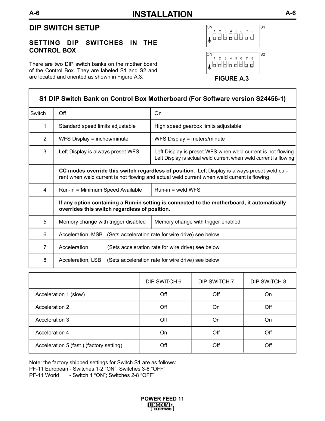
There are two DIP switch banks on the mother board of the Control Box. They are labeled S1 and S2 and are located and oriented as shown in Figure A.3.
ON |
|
|
|
|
|
|
|
| S1 | ||
|
| 1 | 2 | 3 | 4 | 5 | 6 | 7 | 8 |
|
|
|
|
|
|
|
|
|
|
|
|
| S2 |
|
|
|
|
|
|
|
|
|
|
| |
|
|
|
|
|
|
|
|
|
|
| |
|
|
|
|
|
|
|
|
|
|
| |
ON |
|
|
|
|
|
|
|
| |||
|
| 1 | 2 | 3 | 4 | 5 | 6 | 7 | 8 |
|
|
|
|
|
|
|
|
|
|
|
|
|
|
|
|
|
|
|
|
|
|
|
|
|
|
|
|
|
|
|
|
|
|
|
|
|
|
FIGURE A.3
S1 DIP Switch Bank on Control Box Motherboard (For Software version
Switch | Off |
|
|
|
| On |
|
|
|
|
|
|
|
|
|
|
| ||
1 | Standard speed limits adjustable |
| High speed gearbox limits adjustable |
|
| ||||
|
|
|
|
|
|
|
| ||
2 | WFS Display = inches/minute |
| WFS Display = meters/minute |
|
| ||||
|
|
|
|
|
|
|
| ||
3 | Left Display is always preset WFS |
| Left Display is preset WFS when weld current is not flowing |
| |||||
|
|
|
|
|
| Left Display is actual weld current when weld current is flowing |
| ||
|
|
|
|
|
|
| |||
| CC modes override this switch regardless of position. Left Display is always preset weld cur- |
| |||||||
| rent when weld current is not flowing and actual weld current when weld current is flowing |
| |||||||
|
|
|
|
|
|
|
| ||
4 |
|
|
| ||||||
|
|
|
|
|
|
| |||
| If any option containing a |
| |||||||
| overrides this switch regardless of position. |
|
|
| |||||
|
|
|
|
|
|
|
| ||
5 | Memory change with trigger disabled |
| Memory change with trigger enabled |
|
| ||||
|
|
|
|
|
|
|
| ||
6 | Acceleration, MSB | (Sets acceleration rate for wire drive) see below |
|
| |||||
|
|
|
|
|
|
|
| ||
7 | Acceleration | (Sets acceleration rate for wire drive) see below |
|
| |||||
|
|
|
|
|
|
|
| ||
8 | Acceleration, LSB | (Sets acceleration rate for wire drive) see below |
|
| |||||
|
|
|
|
|
|
|
|
|
|
|
|
|
|
|
|
|
|
| |
|
|
|
|
| DIP SWITCH 6 | DIP SWITCH 7 | DIP SWITCH 8 |
| |
|
|
|
|
|
|
|
| ||
Acceleration 1 (slow) |
|
|
| Off | Off | On |
| ||
|
|
|
|
|
|
|
|
| |
Acceleration 2 |
|
|
|
| Off | On | Off |
| |
|
|
|
|
|
|
|
|
| |
Acceleration 3 |
|
|
|
| Off | On | On |
| |
|
|
|
|
|
|
|
|
| |
Acceleration 4 |
|
|
|
| On | Off | Off |
| |
|
|
|
|
|
|
| |||
Acceleration 5 (fast ) (factory setting) |
|
| Off | Off | Off |
| |||
|
|
|
|
| |||||
Note: the factory shipped settings for Switch S1 are as follows: |
|
|
| ||||||
|
|
| |||||||
- Switch 1 “ON”; Switches |
|
|
| ||||||