English Manual
2.1 Configuration switch settings
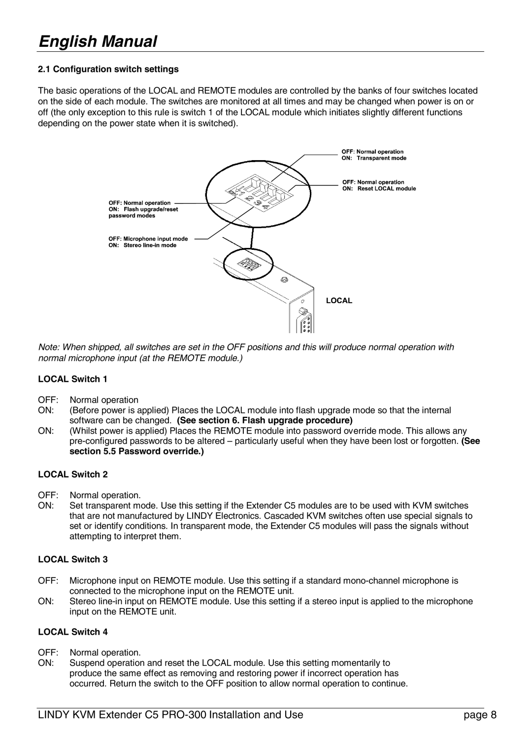
The basic operations of the LOCAL and REMOTE modules are controlled by the banks of four switches located on the side of each module. The switches are monitored at all times and may be changed when power is on or off (the only exception to this rule is switch 1 of the LOCAL module which initiates slightly different functions depending on the power state when it is switched).
Note: When shipped, all switches are set in the OFF positions and this will produce normal operation with normal microphone input (at the REMOTE module.)
LOCAL Switch 1
OFF: | Normal operation |
ON: | (Before power is applied) Places the LOCAL module into flash upgrade mode so that the internal |
| software can be changed. (See section 6. Flash upgrade procedure) |
ON: | (Whilst power is applied) Places the REMOTE module into password override mode. This allows any |
| |
| section 5.5 Password override.) |
LOCAL Switch 2 | |
OFF: | Normal operation. |
ON: | Set transparent mode. Use this setting if the Extender C5 modules are to be used with KVM switches |
| that are not manufactured by LINDY Electronics. Cascaded KVM switches often use special signals to |
| set or identify conditions. In transparent mode, the Extender C5 modules will pass the signals without |
| attempting to interpret them. |
LOCAL Switch 3
OFF: Microphone input on REMOTE module. Use this setting if a standard
ON: Stereo
LOCAL Switch 4
OFF: | Normal operation. |
ON: | Suspend operation and reset the LOCAL module. Use this setting momentarily to |
| produce the same effect as removing and restoring power if incorrect operation has |
| occurred. Return the switch to the OFF position to allow normal operation to continue. |
LINDY KVM Extender C5 | page 8 |