Design Guide
LA-140 Setup and Operating Instructions
5Set Delay Compensation Switch
5A Single Radiator Systems
The position of the delay compensation switch does not matter in single radiator systems.
5B Multiple Radiator Systems
It is necessary to select the correct delay compensation switch setting for each radiator to ensure that each radiator transmits the same signal at exactly the same time in an overlapping ,multiple radiator system. Not setting the delay compensation switch correctly will result in reduced coverage area for the system. See design guide page 16 for determining the correct delay compensation switch setting for each radiator in a multiple radiator system.
Delay Compensation Switch ![]()
6Set Termination Switch
6A Single Radiator Systems
Always set the termination switch to the “ON” position in single radiator systems.
6B Multiple Radiator Systems
Set the termination switch to the “OFF” position on all radiators that are outputting an RF signal to another radiator.
Set the termination switch to the “ON” position on the radiators that are not outputting an RF signal to another radiator.
Termination Switch
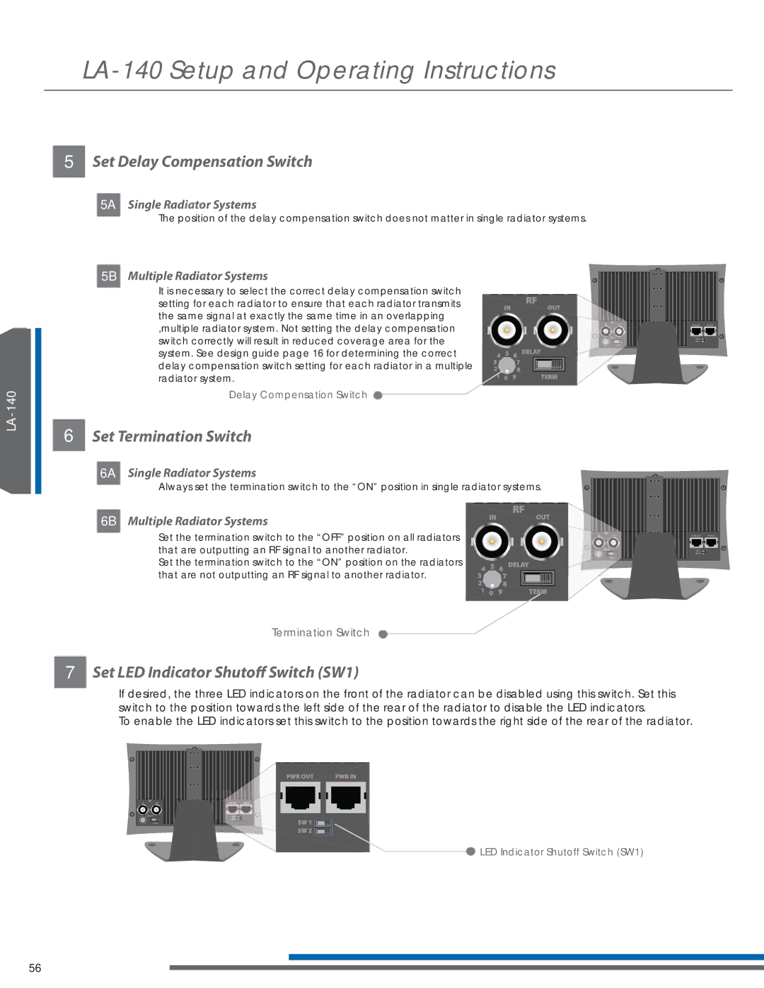
7Set LED Indicator Shutoff Switch (SW1)
If desired, the three LED indicators on the front of the radiator can be disabled using this switch. Set this switch to the position towards the left side of the rear of the radiator to disable the LED indicators.
To enable the LED indicators set this switch to the position towards the right side of the rear of the radiator.
![]() LED Indicator Shutoff Switch (SW1)
LED Indicator Shutoff Switch (SW1)
56