Installation & Operation Manual

5 Vertical direct venting (continued)

Vertical termination – optional concentric vent: Models 400 - 601 Only

￿WARNING

Do not operate the appliance with the rain cap removed or recirculation of combustion products may occur. Water may also collect inside the larger combustion air pipe and flow to the burner enclosure. Failure to follow this warning could result in product damage or improper operation, personal injury, or death.

CAUTION

DO NOT use field-supplied couplings

to extend pipes. Airflow restriction will


occur.

6.

Install the rain cap and the small diameter pipe assembly


into the roof penetration assembly. Ensure the small


diameter pipe is fastened tightly into the rubber adapter


for #CVK3007 installations.

7.

Cement the appliance combustion air and vent pipes to

4.Install the Y concentric fitting pipe assembly up through the structure’s hole and field supplied roof boot/flashing.

NOTICE

Do not allow insulation or other materials

to accumulate inside the pipe assembly


when installing through the hole.

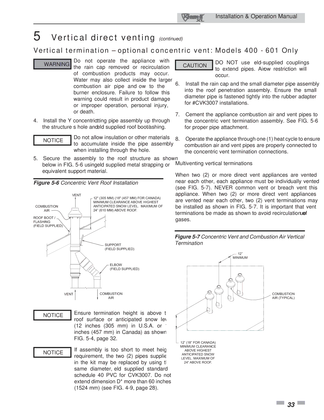
5.Secure the assembly to the roof structure as shown below in FIG. 5-6 using field supplied metal strapping or equivalent support material.

Figure 5-6Concentric Vent Roof Installation

the concentric vent termination assembly. See FIG. 5-6

for proper pipe attachment.

8. Operate the appliance through one (1) heat cycle to ensure

combustion air and vent pipes are properly connected to

the concentric vent termination connections.

Multiventing vertical terminations

When two (2) or more direct vent appliances are vented near each other, each appliance must be individually vented (see FIG. 5-7). NEVER common vent or breach vent this

COMBUSTION

AIR

ROOF BOOT / FLASHING (FIELD SUPPLIED)

VENT

12" (305 MM) (18" (457 MM) FOR CANADA)

MINIMUM CLEARANCE ABOVE HIGHEST ANTICIPATED SNOW LEVEL. MAXIMUM OF 24” (610 MM) ABOVE ROOF.

SUPPORT (FIELD SUPPLIED)

ELBOW

(FIELD SUPPLIED)

appliance. When two (2) or more direct vent appliances are vented near each other, two (2) vent terminations may be installed as shown in FIG. 5-7. It is important that vent terminations be made as shown to avoid recirculation of flue gases.

Figure 5-7Concentric Vent and Combustion Air Vertical Termination

12”

MINIMUM

VENT


COMBUSTION


AIR


NOTICE

Ensure termination height is above the

roof surface or anticipated snow level


(12 inches (305 mm) in U.S.A. or 18


inches (457 mm) in Canada) as shown in


FIG. 5-4, page 32.


If assembly is too short to meet height

NOTICE

requirement, the two (2) pipes supplied


in the kit may be replaced by using the


same diameter, field supplied standard


schedule 40 PVC for CVK3007. Do not


extend dimension D* more than 60 inches


(1524 mm) (see FIG. 4-9, page 28).

COMBUSTION

AIR (TYPICAL)

12” (18” FOR CANADA) MINIMUM CLEARANCE ABOVE HIGHEST ANTICIPATED SNOW LEVEL. MAXIMUM OF 24” ABOVE ROOF.

33

Page 33
Image 33
Lochinvar 400, 801 operation manual Multiventing vertical terminations, Mm see -9

400, 801 specifications

The Lochinvar 801,400 is a cutting-edge solution in the realm of high-efficiency commercial water heating. This model represents a significant advancement in the design and functionality of water heaters, catering primarily to the demands of large-scale facilities like hotels, hospitals, and large industrial operations.

One of the standout features of the Lochinvar 801,400 is its impressive heating capacity, which can produce up to 801,400 BTUs, making it suitable for high-demand applications. This output is crucial for establishments that require a consistent supply of hot water, such as commercial kitchens and laundry facilities. The robust design ensures that it can handle peak demand periods without compromising performance.

Another significant aspect is the innovative use of advanced technology in its operation. The Lochinvar 801,400 integrates smart controls that enhance its efficiency and ease of operation. These controls allow for precise monitoring and adjustment of water temperatures, ensuring that the system operates within optimal parameters while maximizing energy savings. The intelligent monitoring system can provide real-time updates, making it easier for facility managers to keep track of performance and address maintenance needs proactively.

The construction of the Lochinvar 801,400 incorporates durable materials that not only enhance the longevity of the unit but also offer resistance to corrosion and wear. This durability translates into lower maintenance costs and an extended lifespan for the unit, making it a worthwhile investment for businesses.

Moreover, the Lochinvar 801,400 is designed with energy efficiency in mind. It boasts a high thermal efficiency rating, which reduces operational costs and minimizes the carbon footprint of heating operations. This efficiency is critical in today’s environmentally conscious market, where businesses are seeking to reduce their energy consumption and comply with strict regulations.

The design of the Lochinvar 801,400 also prioritizes safety, featuring innovative safety controls and fail-safes that protect both the unit and the users.

In summary, the Lochinvar 801,400 offers a combination of high capacity, advanced technology, durability, and energy efficiency, making it an excellent choice for commercial water heating solutions. As industries continue to evolve, the demand for reliable and efficient water heating solutions like the Lochinvar 801,400 will only increase.