Installation & Operation Manual

13 Diagrams

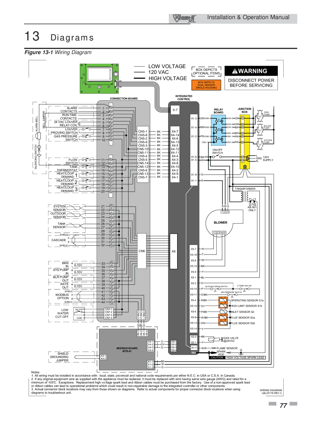
Figure 13-1Wiring Diagram

LOW VOLTAGE 120 VAC HIGH VOLTAGE

BOX DEPICTS

OPTIONAL ITEMS

BOX DEPICTS DUAL SENSOR SINGLE HOUSING

ALARM BELL

BELL JUMPER

SILENCING SWITCH


CONNECTION BOARD


INTEGRATED


CONTROL


ALARM

1


L

N


X-7


RELAY


JUNCTION


CONTACTS

2


BOX


BOARD


DHW

RUN-TIME

3


PUMP

CONTACTS

4


X1-3

OR CN2-4

K1

CN1-5

OR


24 VAC LOUVER

5


CN1-6

OR


RELAY COIL

6


X1-4

BR CN2-2


BOILER

LOUVER


K2

CN1-3

BR

PUMP

7

CN5-1

BK

X4-7


PROVING SWITCH

8


CN1-4

BR


CN5-8

BK

X4-14


GAS PRESSURE

9

X1-2

PR CN2-3

K3

CN1-1

PR


CN5-2

BK

X4-6


SWITCH

10


SYSTEM

CN5-9

BK

X4-13


CN2-1


CN1-2

PR


PUMP


CN5-3

BK

X4-5


CN5-10

BK

X4-12


ON/OFF


CN5-11

BK

X4-11


SWITCH


L


FLOW

11

CN5-4

BK

X4-4

X1-6

BK


120V


CN5-5

BK

X4-3

X1-5

W


GND

SUPPLY

SWITCH

12

CN5-14

BK

X4-8


N


TANK

13

CN5-12

BK

X4-10


THERMOSTAT

14

CN5-6

BK

X4-2


HEAT/LOOP

1

15

CN5-13

BK

X4-9

X1-8

G


DEMAND

16

CN5-7

BK

X4-1


HEAT/LOOP

2

17


X1-1

R


DEMAND

18


HEAT/LOOP

3

19


TRANSFORMER


DEMAND

20


SYSTEM


21


R W G

3.5A


KB 801


SENSOR


22


1

2 3

ONLY


OUTDOOR


23


SENSOR


24


TANK


25


BLOWER


26


SENSOR


27


28


1 2 3 4 5


SHIELD


29


A


30


CASCADE B


31


SHIELD


32


CN6


X6

X5-7

R


X5-16

T


BMS


+


33


X5-8

W


0-10V


IN

-

34


X5-15

BK


SYS PUMP


+

0-10V

35


X5-9

Y


IN


-


36


BLR PUMP


+

0-10V

37


X5-1

BL


OUT


-

38


X5-2

O


RATE


+

0-10V

39


O-TEMP HEX SW


P BLOCKED DRAIN SWITCH


OUT

-

40


X5-10


SHIELD


41


AIR PRESSURE SWITCH


MODBUS


A


42


X5-11

O/BK


-T


OPTION


B


43


X5-4

R/BK


OPERATING SENSOR S1a

SHIELD


44


-T


24 VAC

CN7-1


X5-12

GY


HIGH LIMIT SENSOR S1b


LOW


X5-6

P/BK


-T


WATER


CN7-2

CN8-3

CN8-1 CN8-2


INLET SENSOR S2


CN7-3


-T


CUT-OFF


X5-5


COM

CN7-4


W/BK


FLUE SENSOR S3a


X5-13

PR


-T


R BLG


FLUE SENSOR S3b


X5-14


X6-3

X6-2 X6-1 X6-4


Y


X2-2

BK


GAS VALVE


X4-1

O

X9-1

X2-1

Y


@24VAC


X4-2

GY

X9-2


MODBUS BOARD

X4-3

G

X9-3

X1-7

W/R

FLAME SENSOR G


X4-4


X9-4


SHIELD


MTR-01


TR2


SPARK


X5-1


ROD


GROUNDING


CAUTION

HIGH VOLTAGE SPARK LEAD


X5-2


JUMPER


X1-1

BK


X1-2

W


X1-3

G


Notes:

1.All wiring must be installed in accordance with: local, state, provincial and national code requirements per either N.E.C. in USA or C.S.A. in Canada.

2.If any original equipment wire as supplied with the appliance must be replaced, it must be replaced with wire having same wire gauge (AWG) and rated for a minimum of 105°C. Exceptions: Replacement high vo ltage spark lead and ribbon cables must be purchased from the factory. Use of a non-approved spark lead or ribbon cables can lead to operational problems which could result in non-repairable damage to the integrated controller or other components.

3.Actual connector block locations may vary from those shown on diagrams. Refer to actual components for proper connector block locations when using diagrams to troubleshoot unit.

WIRING DIAGRAM LBL20116 REV C

77

Page 77
Image 77
Lochinvar 400, 801 operation manual Diagrams, LOW Voltage 120 VAC High Voltage

400, 801 specifications

The Lochinvar 801,400 is a cutting-edge solution in the realm of high-efficiency commercial water heating. This model represents a significant advancement in the design and functionality of water heaters, catering primarily to the demands of large-scale facilities like hotels, hospitals, and large industrial operations.

One of the standout features of the Lochinvar 801,400 is its impressive heating capacity, which can produce up to 801,400 BTUs, making it suitable for high-demand applications. This output is crucial for establishments that require a consistent supply of hot water, such as commercial kitchens and laundry facilities. The robust design ensures that it can handle peak demand periods without compromising performance.

Another significant aspect is the innovative use of advanced technology in its operation. The Lochinvar 801,400 integrates smart controls that enhance its efficiency and ease of operation. These controls allow for precise monitoring and adjustment of water temperatures, ensuring that the system operates within optimal parameters while maximizing energy savings. The intelligent monitoring system can provide real-time updates, making it easier for facility managers to keep track of performance and address maintenance needs proactively.

The construction of the Lochinvar 801,400 incorporates durable materials that not only enhance the longevity of the unit but also offer resistance to corrosion and wear. This durability translates into lower maintenance costs and an extended lifespan for the unit, making it a worthwhile investment for businesses.

Moreover, the Lochinvar 801,400 is designed with energy efficiency in mind. It boasts a high thermal efficiency rating, which reduces operational costs and minimizes the carbon footprint of heating operations. This efficiency is critical in today’s environmentally conscious market, where businesses are seeking to reduce their energy consumption and comply with strict regulations.

The design of the Lochinvar 801,400 also prioritizes safety, featuring innovative safety controls and fail-safes that protect both the unit and the users.

In summary, the Lochinvar 801,400 offers a combination of high capacity, advanced technology, durability, and energy efficiency, making it an excellent choice for commercial water heating solutions. As industries continue to evolve, the demand for reliable and efficient water heating solutions like the Lochinvar 801,400 will only increase.