Installation & Operation Manual

6 Hydronic piping (continued)

Flow switch,reliefvalve and temperature and pressure gauge installation

Basic steps are listed below to guide you through the installation of the flow switch, relief valve, and temperature and pressure gauge provided with the unit.

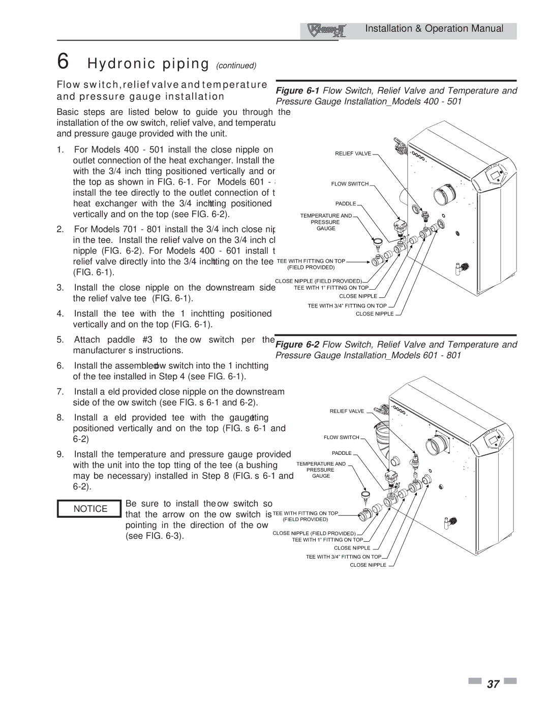
1.For Models 400 - 501 install the close nipple on the outlet connection of the heat exchanger. Install the tee with the 3/4 inch fitting positioned vertically and on the top as shown in FIG. 6-1. For Models 601 - 801 install the tee directly to the outlet connection of the heat exchanger with the 3/4 inch fitting positioned vertically and on the top (see FIG. 6-2).

2.For Models 701 - 801 install the 3/4 inch close nipple in the tee. Install the relief valve on the 3/4 inch close nipple (FIG. 6-2). For Models 400 - 601 install the relief valve directly into the 3/4 inch fitting on the tee (FIG. 6-1).

3.Install the close nipple on the downstream side of the relief valve tee (FIG. 6-1).

4.Install the tee with the 1 inch fitting positioned vertically and on the top (FIG. 6-1).

Figure 6-1Flow Switch, Relief Valve and Temperature and Pressure Gauge Installation_Models 400 - 501

RELIEF VALVE

FLOW SWITCH

PADDLE

TEMPERATURE AND

PRESSURE

GAUGE

TEE WITH FITTING ON TOP (FIELD PROVIDED)

CLOSE NIPPLE (FIELD PROVIDED)

TEE WITH 1” FITTING ON TOP

CLOSE NIPPLE

TEE WITH 3/4” FITTING ON TOP

CLOSE NIPPLE

5.Attach paddle #3 to the flow switch per the manufacturer’s instructions.

6.Install the assembled flow switch into the 1 inch fitting of the tee installed in Step 4 (see FIG. 6-1).

7.Install a field provided close nipple on the downstream side of the flow switch (see FIG.’s 6-1 and 6-2).

8.Install a field provided tee with the gauge fitting positioned vertically and on the top (FIG.’s 6-1 and 6-2)

9.Install the temperature and pressure gauge provided with the unit into the top fitting of the tee (a bushing may be necessary) installed in Step 8 (FIG.’s 6-1 and 6-2).

NOTICE

Be sure to install the flow switch so

that the arrow on the flow switch is


pointing in the direction of the flow


(see FIG. 6-3).

Figure 6-2Flow Switch, Relief Valve and Temperature and Pressure Gauge Installation_Models 601 - 801

RELIEF VALVE

FLOW SWITCH

PADDLE

TEMPERATURE AND

PRESSURE

GAUGE

TEE WITH FITTING ON TOP

(FIELD PROVIDED)

CLOSE NIPPLE (FIELD PROVIDED)

TEE WITH 1” FITTING ON TOP

CLOSE NIPPLE

TEE WITH 3/4” FITTING ON TOP

CLOSE NIPPLE

37

Page 37
Image 37
Lochinvar 400, 801 operation manual Hydronic piping

400, 801 specifications

The Lochinvar 801,400 is a cutting-edge solution in the realm of high-efficiency commercial water heating. This model represents a significant advancement in the design and functionality of water heaters, catering primarily to the demands of large-scale facilities like hotels, hospitals, and large industrial operations.

One of the standout features of the Lochinvar 801,400 is its impressive heating capacity, which can produce up to 801,400 BTUs, making it suitable for high-demand applications. This output is crucial for establishments that require a consistent supply of hot water, such as commercial kitchens and laundry facilities. The robust design ensures that it can handle peak demand periods without compromising performance.

Another significant aspect is the innovative use of advanced technology in its operation. The Lochinvar 801,400 integrates smart controls that enhance its efficiency and ease of operation. These controls allow for precise monitoring and adjustment of water temperatures, ensuring that the system operates within optimal parameters while maximizing energy savings. The intelligent monitoring system can provide real-time updates, making it easier for facility managers to keep track of performance and address maintenance needs proactively.

The construction of the Lochinvar 801,400 incorporates durable materials that not only enhance the longevity of the unit but also offer resistance to corrosion and wear. This durability translates into lower maintenance costs and an extended lifespan for the unit, making it a worthwhile investment for businesses.

Moreover, the Lochinvar 801,400 is designed with energy efficiency in mind. It boasts a high thermal efficiency rating, which reduces operational costs and minimizes the carbon footprint of heating operations. This efficiency is critical in today’s environmentally conscious market, where businesses are seeking to reduce their energy consumption and comply with strict regulations.

The design of the Lochinvar 801,400 also prioritizes safety, featuring innovative safety controls and fail-safes that protect both the unit and the users.

In summary, the Lochinvar 801,400 offers a combination of high capacity, advanced technology, durability, and energy efficiency, making it an excellent choice for commercial water heating solutions. As industries continue to evolve, the demand for reliable and efficient water heating solutions like the Lochinvar 801,400 will only increase.