
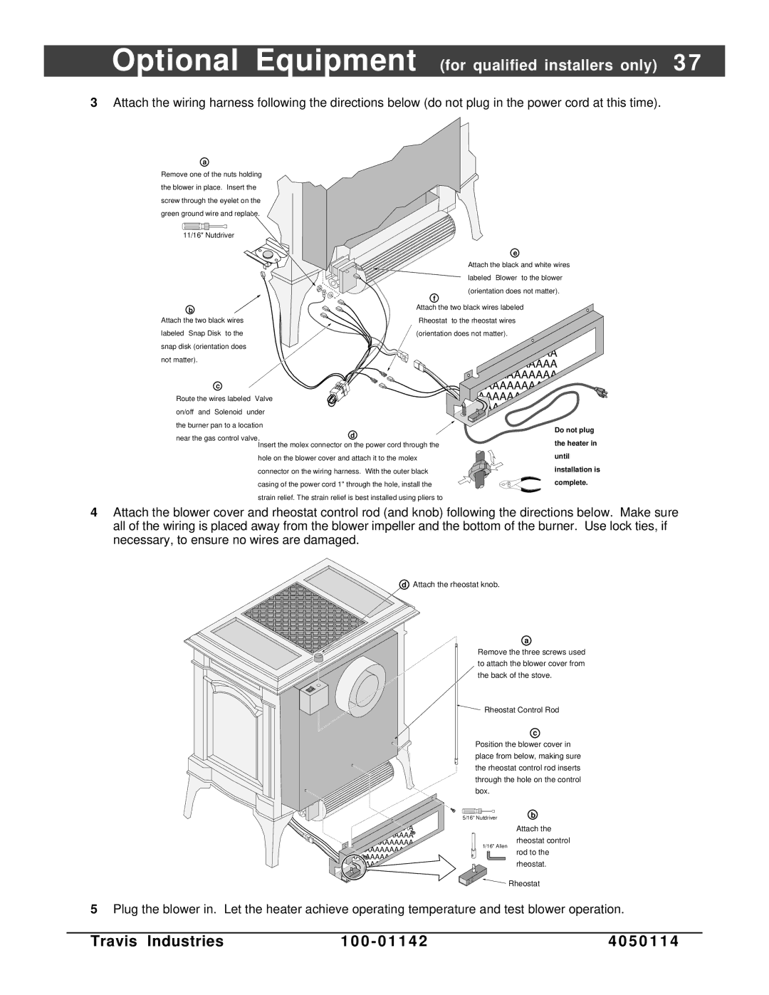
Direct Vent Freestanding Stove specifications
The Lopi Direct Vent Freestanding Stove stands out as a leading choice for homeowners seeking efficient and elegant heating solutions. Known for its innovative design and advanced technology, the stove combines aesthetic appeal with exceptional performance, making it an ideal addition to any living space.One of the main features of the Lopi Direct Vent Freestanding Stove is its direct venting system. This technology allows the stove to draw air from outside for combustion and eject exhaust gases outdoors, ensuring optimal indoor air quality. This not only enhances efficiency but also eliminates the need for a traditional chimney, making installation simpler and versatile.
The stove's design is both modern and traditional, featuring clean lines and a variety of finishes to complement any décor. Available in different sizes, the Lopi stove can fit comfortably in various spaces while providing powerful heating. Its large viewing window invites warmth and ambiance, allowing users to enjoy the mesmerizing flames without compromising heat output.
Boasting impressive heating capabilities, the Lopi Direct Vent Freestanding Stove has a high BTU output, effectively warming spaces even in the coldest of climates. The unit is equipped with a robust heat exchanger that maximizes heat retention while minimizing fuel consumption. Furthermore, the stove can operate using either natural gas or propane, offering flexibility based on availability and preference.
In terms of efficiency, many models in this line come with an EPA certification, demonstrating a commitment to environmentally friendly practices. With features such as adjustable flame settings and a thermostatic remote control, users can easily customize their heating experience, ensuring comfort at all times.
Safety is also a priority with the Lopi Direct Vent Freestanding Stove. It includes built-in safety features such as a protective screen and cool-to-the-touch body, making it suitable for homes with children or pets. The durable construction ensures longevity, with high-quality materials designed to withstand the test of time.
In summary, the Lopi Direct Vent Freestanding Stove combines sleek aesthetics with cutting-edge technology to deliver an unparalleled heating solution. With its array of features, efficiency, and safety measures, it not only enhances home comfort but also adds a touch of elegance to any living environment. Whether enjoying the warmth on a chilly evening or creating a cozy atmosphere, the Lopi stove stands out as a top choice for modern homeowners.