MRD500VR
Dear Magnavox product owner
For Customer Use
Model No Serial No
Safety and General Information
Safety Precautions
Declaration of Conformity
Model Number MRD500VR Trade Name Magnavox
Table of Contents
Introduction
Playable Discs and Video Cassettes
Hookups
Determining the best possible connection
Before you begin
Remember
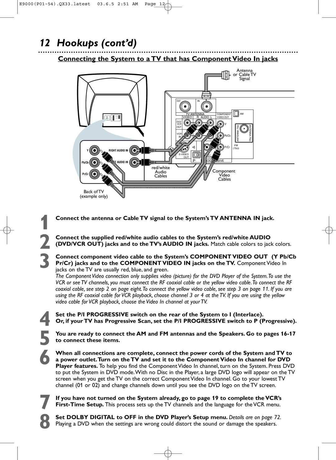
Hookups cont’d
Antenna
With this connection
Helpful Hint
To watch one channel while recording another
Example only
Antenna Or Cable TV Signal
Red/white Component Audio Cables Video
Connecting the System to a TV that has an S-Video In jack
Video Cable
Connecting the System to a TV and a Stereo
Back of TV example only Yellow Video Cable
Coaxial Digital Audio Cable
Antenna Connections
AM Antenna
FM Antenna
Speaker Setup
Connecting the speaker wires to the speaker jacks
Setting up Surround Sound
Speaker setup
Putting Batteries in the Remote Control
Using the Remote Control
Recycling Guidelines/Battery Safety
First-time Setup
1Turn on the TV
Other tape playback features are on pages
Video Cassette Playback
Read and follow the steps below to play a tape
1Turn on the TV 2Insert a tape in the System
Disc Playback
4Insert a Disc
Remote Control
Remote Control cont’d
Front Panel
Front Panel cont’d
Display Panel
Display Messages
Rear Panel
Channel Setup
Press o or p to select Channel SET UP. Then, press B
Press o or p to select Auto SET UP. Press B
Press VCR, then press DISC/MENU so the main menu appears
Channel Setup cont’d
Adding/Deleting Channels
Clock VCR
Press o or p to select Clock SET, then press B
While the Month space is flashing, press o or p
Until the month appears. Then, press B
Clock VCR cont’d
Language VCR
VCR Status Displays
Press Display again to remove all the displays
Videotape Recording
Recording Prevention
Begins, press Stop C
Details about tape speed are on
Recording One Channel/Watching Another
One-Touch Recording
Stopping an OTR
2Press Record I on the front of the System
You cannot pause an OTR
Put the unit in VCR mode if necessary
Unit in VCR mode if necessary
Rerecording Tape Duplication
System Plays tape
Timer Recording
Set the clock. Details are on pages
Press o or p to select an empty program.Then, press
Press o or p to select ONCE, DAILY, or Weekly
Timer Recording cont’d
Press o or p until the month appears beside Date
Next, press o or p until the day appears.Then, press
Details are on page nine
Cancelling Timer Recordings
10Press C-RESET/CLEARto store the timer recording
DVD to Videotape Duplication
This will be possible only if the DVD is not copy protected
Press VCR so the red VCR light appears on the front
System
Repeat Play
Follow the steps below to play a videotape repeatedly
Press o or p to select Auto Repeat
Press B so on appears next to Auto Repeat
Tape Counter
Time Search, Index Search
Time Search
Index Search
Special Effects Playback
Forward and Reverse Searching SP/LP/SLP
Super High Speed Searching LP/SLP
Viewing a Still Picture
Automatic Operation Features
Multi-Channel Television Sound
Understanding Displays
Press DISC/MENU to remove the menu
Hi-Fi Stereo
Press o or p to select Audio OUT. Then, press B
Press o or p to select HIFI. on will appear beside Hifi
Digital Sound, Surround Sound
Digital Sound
Surround Sound
Delay Time
Press DVD to put the System in DVD mode. The red
Delay Time cont’d
Delay Time will be selected. Press OK
Press SETUP/PROG to remove the menu
Press p to select 5.1CH, then press OK
Speaker Balance
To stop Disc play if necessary
11Press SETUP/PROG to remove the menu
Speaker Balance cont’d
Press p to select BALANCE, then press OK
Test will be selected. Press OK
Using the Title Menu
DVD Disc Menus
With a DVD in the System, press DISC/MENU.
Press o, p, s, or B to select an item, then press OK
Fast Forward/Reverse Search
During playback, press FF g or REW h
Press Play B to return to normal playback
Title/Chapter Playback,Time Playback
Title/Chapter Playback
Time Playback
Using the Number Buttons
Using Search Mode
Using Skip i /CH o or Skip j/ CH p
Paused and Step-by-Step Playback, Resume
Paused and Step-by-Step Playback
Resume
Until the repeat mode you want appears on the TV
Repeat, A-B Repeat
Repeat
During DVD or Audio CD playback, press Repeat
Markers
Subtitles
Camera Angles
Are available /6. After a few seconds, the subtitles will
Press DVD
Slow Motion, Zoom
Slow Motion
Zoom
Press Pause F during DVD playback
Programs
Random Play
While play is stopped, press MODE/SPEED
While the Random screen appears, press
Parental Controls Password
Press B to select Lock, then press OK. The first
Press OK.You are finished! Go to step
Press p to select CHANGE, then press OK
Parental Levels
Press B to select Custom at the top of the menu
Then press OK. This menu will appear
Press B to select Lock, then press OK
Audio Language, Stereo Sound
Audio Language
Stereo Sound
MP3/JPEG/Picture CD Playback
Put a Disc in the DVD Player of the System
To stop playback, press Stop C
Jpeg Files have the icon
68 MP3/JPEG/Picture CD Displays
Press Display again to remove the display
When Disc play is stopped, press SETUP/PROG.
Press SETUP/PROG to remove the menus
Display
Display, then press OK
While playback is stopped, press SETUP/PROG.
Language
Language cont’d
Language Codes
Press o or p to select a language, then press OK.
MENU, press four Number buttons to enter
Audio
Press B to select Audio at the top
Menu, then press OK
Press o or p to select DRC, Dolby DIGITAL, or
On-Screen Displays
DVD Display
Audio CD Display
Black Level
Black Level
During DVD playback, press MODE/SPEED so the Black
Within 10 seconds, press OK repeatedly to choose on
To set up preset radio stations, see
Selecting Radio Stations
Press Tuner to select Tuner mode. The red Tuner
Press AUDIO/BAND to select FM or AM
Preset Radio Stations
Automatic Presetting
Manual Presetting
Glossary, Specifications
Specifications
Glossary
Helpful Hints
Helpful Hints cont’d
Power Failure
VCR will not perform a timer recording
VCR will not record a TV program
Number buttons won’t work for TV channels above
Line Input mode
Cleaning the Video Heads
You cannot insert a video cassette
You cannot remove the tape
Limited Warranty
Contact Magnavox to arrange an exchange
Please contact Magnavox at French Speaking
Page
Information Index
Controls