8 EN

INSTALLING YOUR NEW VCR (cont.)

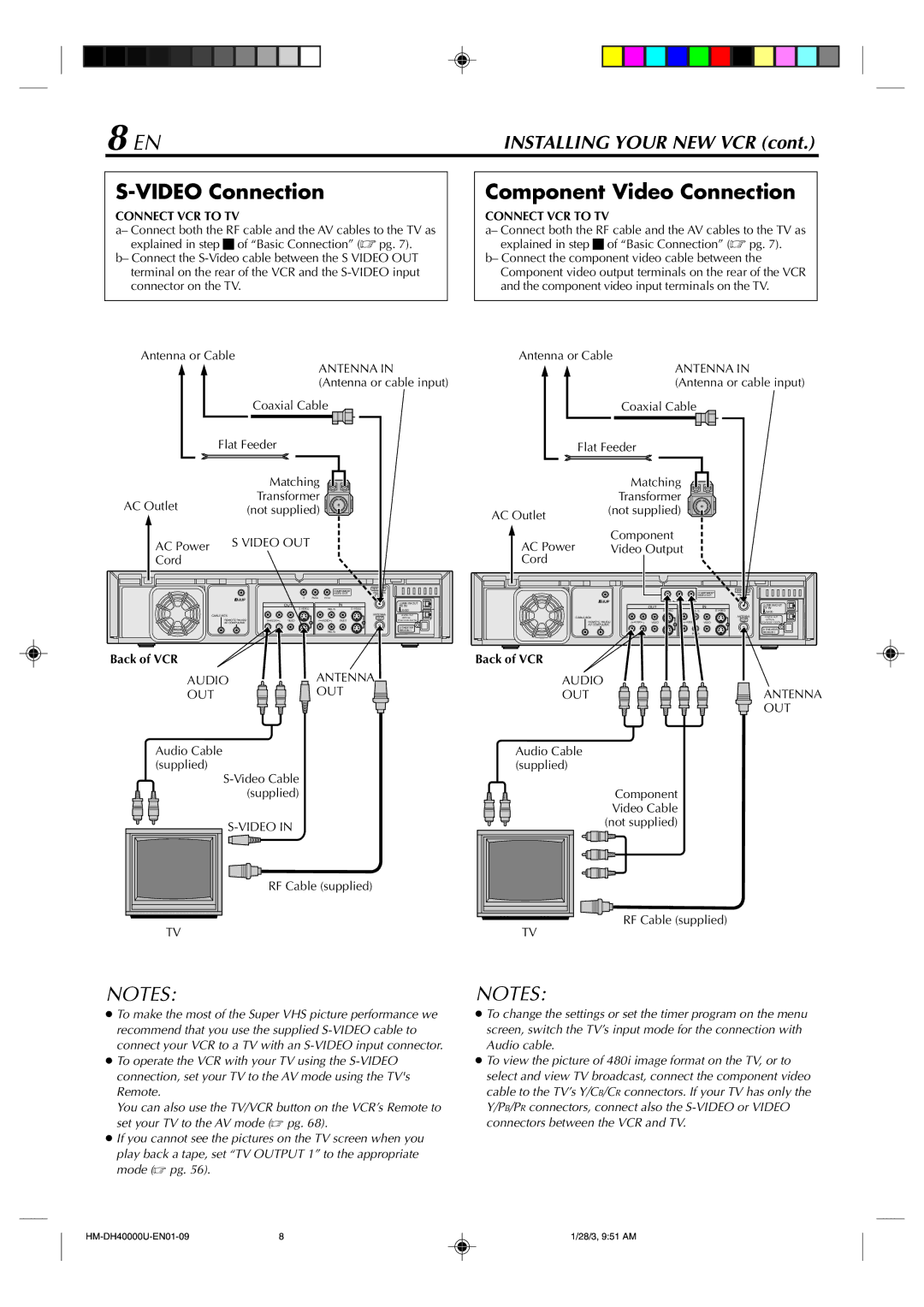
S-VIDEO Connection

CONNECT VCR TO TV

a– Connect both the RF cable and the AV cables to the TV as explained in step 3 of “Basic Connection” ( pg. 7).

b– Connect the S-Video cable between the S VIDEO OUT terminal on the rear of the VCR and the S-VIDEO input connector on the TV.

Antenna or Cable


ANTENNA IN


(Antenna or cable input)


Coaxial Cable


Flat Feeder


Matching


AC Outlet


Transformer


(not supplied)


AC Power

S VIDEO OUT


Cord


COMPONENT

VHF/UHF


VIDEO OUT

ANTENNA


Y

PB/CB PR/CR


IN


OUT


IN


i.LINK IN/OUT


DV IN


S VIDEO

IN(L-1)

S VIDEO


S400


CABLE BOX


ANTENNA

DIGITAL OUT


REMOTE PAUSE/

R AUDIO L VIDEO

R AUDIO L

VIDEO

OUT

OPTICAL


PCM/DOLBY DIGITAL


AV COMPULINK


D THEATER


IN(L-2)


REGION 1

Back of VCR

AUDIO

ANTENNA

OUT

OUT

Audio Cable (supplied)

S-Video Cable (supplied)

S-VIDEO IN

RF Cable (supplied)

TV

Component Video Connection

CONNECT VCR TO TV

a– Connect both the RF cable and the AV cables to the TV as explained in step 3 of “Basic Connection” ( pg. 7).

b– Connect the component video cable between the Component video output terminals on the rear of the VCR and the component video input terminals on the TV.

Antenna or Cable

ANTENNA IN (Antenna or cable input)


Coaxial Cable


Flat Feeder


Matching


Transformer

AC Outlet

(not supplied)


Component

AC Power Video Output

Cord


COMPONENT

VHF/UHF


ANTENNA


VIDEO OUT

B

B

IN


OUT


IN

i.LINK IN/OUT


DV IN


S VIDEO

IN(L-1)

S VIDEO

S400

CABLE BOX


ANTENNA

DIGITAL OUT

REMOTE PAUSE/

R AUDIO L


R AUDIO L

OUT

OPTICAL

VIDEO

VIDEO

PCM/DOLBY DIGITAL

AV COMPULINK


D THEATER


IN(L-2)


REGION 1

Back of VCR


AUDIO

ANTENNA

OUT


OUT

Audio Cable (supplied)

Component Video Cable (not supplied)

RF Cable (supplied)

TV

NOTES:

To make the most of the Super VHS picture performance we recommend that you use the supplied S-VIDEO cable to connect your VCR to a TV with an S-VIDEO input connector.

To operate the VCR with your TV using the S-VIDEO connection, set your TV to the AV mode using the TV's Remote.

You can also use the TV/VCR button on the VCR’s Remote to set your TV to the AV mode ( pg. 68).

If you cannot see the pictures on the TV screen when you play back a tape, set “TV OUTPUT 1” to the appropriate mode ( pg. 56).

NOTES:

To change the settings or set the timer program on the menu screen, switch the TV’s input mode for the connection with Audio cable.

To view the picture of 480i image format on the TV, or to select and view TV broadcast, connect the component video cable to the TV’s Y/CB/CR connectors. If your TV has only the Y/PB/PR connectors, connect also the S-VIDEO or VIDEO connectors between the VCR and TV.

HM-DH40000U-EN01-09

8

1/28/3, 9:51 AM

Page 8
Image 8
Marantz MV8300_U1B manual Video Connection

MV8300_U1B specifications

The Marantz MV8300_U1B is a state-of-the-art component that exemplifies high-fidelity audio reproduction, tailored for music enthusiasts who appreciate both quality and craftsmanship. As part of Marantz's esteemed line of audio products, the MV8300_U1B combines advanced technology with practical usability, making it a standout choice for home theater setups and dedicated audio systems.

One of the most notable features of the MV8300_U1B is its exceptional power output, capable of delivering a robust performance that effortlessly drives demanding speakers. With a substantial total harmonic distortion rating, the amplifier ensures that the audio signal remains clean and undistorted, allowing listeners to experience music as it was intended by the artists. The unit's power rating makes it suitable for various settings, whether for intimate listening experiences or grand home theater presentations.

Incorporating advanced class D amplification, the MV8300_U1B achieves high efficiency without compromising sound quality. This technology allows for a more compact design while still providing significant power reserves, resulting in impressive dynamic range and clarity. The amplifier is engineered to produce an immersive soundstage with detailed imaging, providing listeners with a unique auditory experience.

Connectivity options are plentiful on the MV8300_U1B, including multiple line inputs for versatile integration with various audio sources. The unit also features built-in DAC capabilities, allowing for the conversion of high-resolution digital audio formats, which adds convenience for those who stream music and use digital devices. With Marantz's commitment to quality craftsmanship, the MV8300_U1B is built using premium components, further enhancing its performance and reliability.

The design of the MV8300_U1B reflects Marantz's dedication to aesthetics as well as functionality. Its sleek, modern appearance is characterized by a minimalist front panel, intuitive controls, and LED indicators that provide clear feedback. The robust construction not only contributes to its durability but also helps minimize vibration, ensuring that audio performance remains unaffected.

Additionally, the MV8300_U1B includes advanced thermal management systems that prevent overheating, allowing for continuous operation during long listening sessions. This ensures that the amplifier maintains its performance and longevity, providing owners with a reliable audio solution for years to come.

In conclusion, the Marantz MV8300_U1B is an excellent choice for audiophiles seeking a powerful amplifier that combines cutting-edge technology with superb audio reproduction. Its impressive features, robust build quality, and aesthetic appeal make it an ideal addition to any serious audio setup.