CF-29
For U.K This apparatus must be earthed for your safety
How to replace the fuse
Laser Safety Information
Page
Page
Contents
Basic Procedure
Diagnosis Procedure
Flow Chart
Troubleshooting
Table of errors classified by beep sounds
Error Diagnosis by Checking Beep Signal Sound
Outline of Post
Stuck key
02F4 Eisa Cmos not writable
Preparation
Equipment
Self Diagnosis Test
Speaker Test
Vesa Mode Test
CPU A20 Gate Test
Cache ON/OFF Test
LAN Test
Modem Test Wireless LAN Test CD Test
Test Selection
Error Messages and Troubleshooting
Wiring Connection Diagram
Removing the HDD
Removing the Battery Pack, HDD Pack and FDD Pack
HDD FPC
HDD
Remove the KB Cable Cover, Keyboard and Pcmcia Protector
Removing the Dimm Cover and Bottom Cover
Removing the KBD PCB, MDC Modem and LCD Cable/MIC Frame
Removing the Speaker
Removing the Wireless Module
PAD SW FFC
Removing the TP PCB
Remove the HDD Main FPC
Removing the IO PCB
Removing the Handle and Power
Removing LCD Unit Removing LCD Rear Cabinet, Hinge Hinge R
Removing the Antenna PCB L
Removing the Inverter PCB, TS PCB and LCD Unit
Arranging the Antenna L and R Cables
Setting the Antenna PCB L and R
View a
Setting the Inverter PCB, TS PCB and LCD Unit
Attaching the Touch Screen Panel
TS FPC
Arranging the Inverter PCB
View B2
Arranging the LCD Back Holder
LCD Unit LCD Hold Plate L LCD Plate R LCD Metal Damper
TS PCB
Attaching the Inverter PCB and TS PCB
PCB
Arranging the Cables
View E
Setting the LCD unit
Setting the LCD Rear Cabinet, Hinge L and Hinge R
Setting the Handle and Power SW
PW LED PCB
Arranging the SW LED PCB
SW LED PCB
Arranging the Power SW Cable
Arrange the IO FPC
Setting the IO PCB
IO FPC
IO FPC LID SW
IO PCB
Setting the IO FPC
IO PCB LID SW
Attaching the Cable Sheet, Insulation Sheet and the Sheet
Setting the TP PCB
LED FFC
TP PCB
Arranging the HDD Main FPC
Setting the HDD Main FPC
No4
Setting the LAN Cable and Modem Cable
Main PCB LAN Cable Clamper Slot
Setting the Main PCB
View D View C
Setting the RTC Battery
Setting the PAD SW FFC Cover
View C
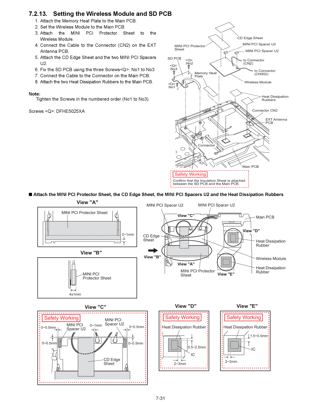
Setting the Wireless Module and SD PCB
Mini PCI
Attaching the Memory Heat Plate
Setting the Speaker
Arranging the Dimm Cover and the Dimm Radiation Sheet
Setting the Dimm Cover and Bottom Cover
Attaching the Sheet to the MDC Modem
Setting the KBD PCB, MDC Modem and LCD Cable/MIC Frame
Arranging the Cables and setting the LCD Cable/MIC Frame
Arranging the Keyboard
Setting the KB Cable Cover, Keyboard and Pcmcia Protector
Hinge Cover L No2 C No10 B No3 C No11 No4 No7 No5
Attaching the Sheet
Setting the HDD
Setting the Battery Pack, the HDD Pack and the FDD Pack
Exploded View
19 ± 0.02 N.m
441 + 0.049 N.m
19 + 0.02 N.m 2.0 + 0.2 kgf.cm 45 + 0.05 N.m
Screw tightening torque
19 + 0.02 N.m
Screw tightening torque
DFJS865ZA Power SW Cable
Wireless LAN Module
Battery Pack DFJS954ZA Modem Cable
Description QTY
DFUQ0099ZA Power SW Spring
Power SW Assy
Power SW Knob
Power SW ARM
PC Latch Assy
DFHR3497YA Power SW Sheet
PC Latch Lever
DFMD1161ZA PC Latch Angle
DFGT1055ZA Bottom Cover Sheet a
DFMX1006ZA Cable Sheet
DFHG370ZA Foot Rubber
DFHP7162ZA HD FPC Tape
DFHM0330YB CN Spacer
DFHM0304YB MDC Spacer
DRHM5118ZA Screw
DFHR3713ZA Mini PCI Spacer U2
DFHR3743YA Power LED Packing Sheet
DFHR3747ZA Power SW PWB Cushion
DFHR3778ZA Battery Angle Sheet W
DFMD7A49ZA Connector Ring
DFHR4050ZA TUBE, LED
DFHR5440YA GUIDE, FDD Connector
DFHR8295ZC LS DAMPER, UNDER-1
DFHR8296ZB LS DAMPER, UNDER-2
QTY
RTC Battery
EEFCD0D151ER
Page
Page
Page
Page
Page
EEFCX0D331R
EEFCX0D221R
EEFCD0D101ER
ECJ2FF1A106Z
EEFUD0J151ER
EEFCD0G101ER
EEFCX0J101R
DCUI1C106HDB
EEFUE0J181ER
Thermistor
Connector
Diode
DED10QS04TL Diode
IC, USB Power Control
FUSE, 5A
FUSE, 2A
IC, Gate Logic
IC, Audio AMP
IC, Eeprom
IC, Security Chip
Inductor DDB5Z031J-L
Inductor
Inductor DDB5Z021C-Y
Inductor ETQP4LR56WFC
DETA144EETL Transistor
Transistor B1GKCFJN0004
ERJ2RKF27R4X
ERJ2GEJ681X
ERJ2RKF54R9X
ERJ2RKF39R2X
ERJ2GEJ750X
ERJ2GEJ562X
ERJ2RKF2210X
ERJ2RKF1000X
ERJ2GEJ103X RESISTOR, 1/16W
ERJ2RKF80R6X RESISTOR, 1/16W
ERJ2GEJ101X
ERJ2GEJ222X
ERJ2RKF1501X
ERJ2RKF1500X
ERJ2GEJ390X
ERJ2RKF2550X
Resistor Array
ERJ2GEJ102X RESISTOR, 1/16W, 1KΩ
ERJ2GEJ1R0X RESISTOR, 1/16W, 1Ω
ERJ2GEJ120X
DEARA8AJ103M Resistor Array
ERJ2RKF22R6X
ERJ2GEJ472X
ERJ2GEJ106X RESISTOR, 1/16W, 10MΩ
ERJ2GEJ203X RESISTOR, 1/16W, 20KΩ
ERJ2GEJ105X RESISTOR, 1/16W, 1MΩ
ERJ6GEYJ680V
DEARA8CJ330M Resistor Array
ERJ2RKD154X
ERJ2GEJ100X
ERJ2RKF3010X
ERJ2GEJ333X RESISTOR, 1/16W, 33KΩ
ERJ2GEJ363X RESISTOR, 1/16W, 36KΩ
ERJ2GEJ223X RESISTOR, 1/16W, 22KΩ
ERJ2GEJ683X RESISTOR, 1/16W, 68KΩ
ERJ2RKF1600X
ERJ2RKF5602X RESISTOR, 1/16W, 56KΩ
ERJ2RKF2150X
ERJ2RKF7501X
ERJ2GEJ154X
ERJ2RHD3652X
ERA3EKB1623V
ERA3EEB1692V
DDB5Z024E-L Inductor
DDB5Z021G-Y Inductor
Poly SW
LED
ERJ3GEYJ102V RESISTOR, 1/16W, 1KΩ
IC, Flat PAD Controller
B1GKCFJN0004 Transistor
ERJ2GEJ822X
ERJ2GEJ224X
Resistor Array EVQPLDA15
LED EVQPLDA15