ALL ABOUT IMAGE RECOGNITION & PROCESSING
Table of Contents
1.About this document | 2 | ||
2. Before reading this document | 2 | ||
3. Unit Description | 3 | ||
1) Front Panel | 3 | ||
2) Rear Panel | |||
4 | |||
4. Installation | 5 | ||
5. Operation | 9 | ||
1) | 9 | ||
2) Record | 10 | ||
3) Play | 13 | ||
4) Setting | 15 | ||
1 | Basic Operation | 15 | |
2 | DISPLAY SETUP | 16 | |
3 | CAMERA SETUP | 17 | |
4 | TIME/DATE SETUP | 19 | |
5 | ALARM/MOTION SETUP | 20 | |
6 | RECORD SETUP | 23 | |
7 | TCP/IP SETUP | 24 | |
8 | MISCELLANEOUS SETUP | 25 | |
6. Specification & Configuration | 29 | ||
1) SPECIFICATIONS | 29 | ||
2) Stand alone DVMR | 30 | ||
3) | 30 | ||
4) Arrangement | 31 | ||
|
|
| |
ALL ABOUT IMAGE RECOGNITION & PROCESSING
6. Specification and
Configuration
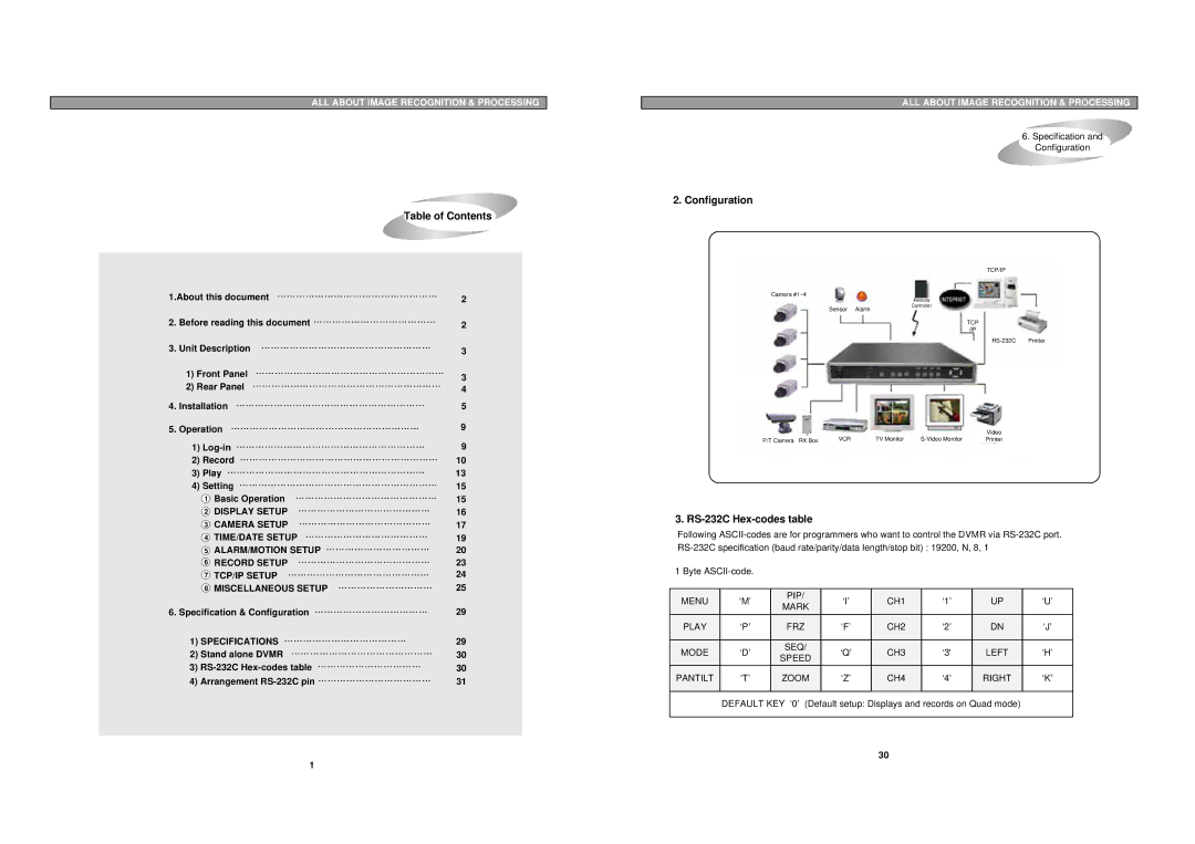
2. Configuration
TCP/IP
Camera #1~4
|
| Remote | |
|
| Controller | |
Sensor Alarm | |||
|
| ||
|
|
|
TCP /IP
|
|
|
|
|
|
|
|
|
|
|
|
|
|
|
|
|
|
|
|
|
|
|
|
|
|
|
|
|
|
| Video |
|
|
| VCR |
| TV Monitor |
|
|
| Printer |
| |
P/T Camera RX Box |
|
| ||||||||
|
|
|
|
|
|
|
|
|
|
|
|
|
|
|
|
|
|
|
|
|
|
|
|
|
|
|
|
|
|
|
|
|
3. RS-232C Hex-codes table
Following
1 Byte
MENU | ‘M’ | PIP/ | ‘I’ | CH1 | ‘1’ | UP | ‘U’ | |
MARK | ||||||||
|
|
|
|
|
|
| ||
PLAY | ‘P’ | FRZ | ‘F’ | CH2 | ‘2’ | DN | ‘J’ | |
|
|
|
|
|
|
|
| |
MODE | ‘D’ | SEQ/ | ‘Q’ | CH3 | ‘3' | LEFT | ‘H’ | |
SPEED | ||||||||
|
|
|
|
|
|
| ||
PANTILT | ‘T’ | ZOOM | ‘Z’ | CH4 | ‘4’ | RIGHT | ‘K’ | |
|
|
|
|
|
|
|
| |
| DEFAULT KEY ‘0’ (Default setup: Displays and records on Quad mode) |
| ||||||
|
|
|
|
|
|
|
| |
|
|
|
| 30 |
|
|
| |
1