Testing Procedures
!WARNING
To avoid risk of electrical shock, personal injury or death; disconnect power to microwave oven and discharge the high voltage capacitor before servicing, unless testing requires power.
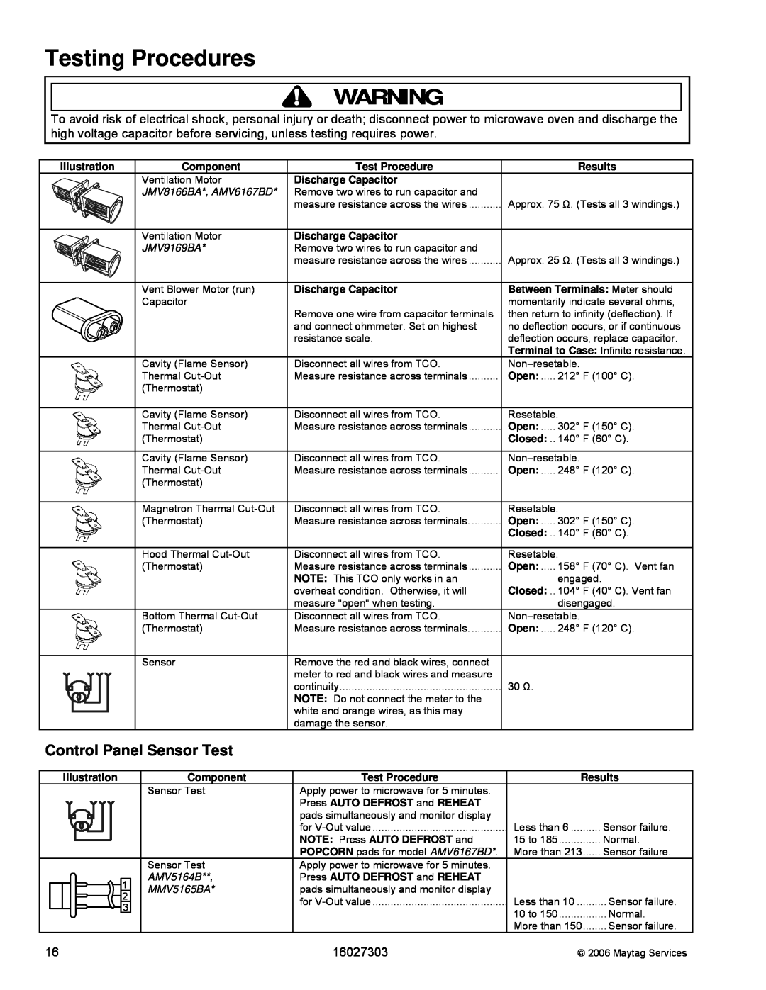
Illustration | Component | Test Procedure |
| Ventilation Motor | Discharge Capacitor |
| JMV8166BA*, AMV6167BD* | Remove two wires to run capacitor and |
|
| measure resistance across the wires |
| Ventilation Motor | Discharge Capacitor |
| JMV9169BA* | Remove two wires to run capacitor and |
|
| measure resistance across the wires |
| Vent Blower Motor (run) | Discharge Capacitor |
| Capacitor | Remove one wire from capacitor terminals |
|
| |
|
| and connect ohmmeter. Set on highest |
|
| resistance scale. |
| Cavity (Flame Sensor) | Disconnect all wires from TCO. |
| Thermal | Measure resistance across terminals |
| (Thermostat) |
|
| Cavity (Flame Sensor) | Disconnect all wires from TCO. |
| Thermal | Measure resistance across terminals |
| (Thermostat) |
|
| Cavity (Flame Sensor) | Disconnect all wires from TCO. |
| Thermal | Measure resistance across terminals |
| (Thermostat) |
|
| Magnetron Thermal | Disconnect all wires from TCO. |
| (Thermostat) | Measure resistance across terminals |
| Hood Thermal | Disconnect all wires from TCO. |
| (Thermostat) | Measure resistance across terminals |
|
| NOTE: This TCO only works in an |
|
| overheat condition. Otherwise, it will |
|
| measure "open" when testing. |
| Bottom Thermal | Disconnect all wires from TCO. |
| (Thermostat) | Measure resistance across terminals |
| Sensor | Remove the red and black wires, connect |
|
| meter to red and black wires and measure |
|
| continuity |
|
| NOTE: Do not connect the meter to the |
|
| white and orange wires, as this may |
|
| damage the sensor. |
Results
Approx. 75 Ω. (Tests all 3 windings.)
Approx. 25 Ω. (Tests all 3 windings.)
Between Terminals: Meter should momentarily indicate several ohms, then return to infinity (deflection). If no deflection occurs, or if continuous deflection occurs, replace capacitor. Terminal to Case: Infinite resistance.
Open: ..... 212° F (100° C).
Resetable.
Open: ..... 302° F (150° C).
Closed: .. 140° F (60° C).
Open: ..... 248° F (120° C).
Resetable.
Open: ..... 302° F (150° C).
Closed: .. 140° F (60° C).
Resetable.
Open: ..... 158° F (70° C). Vent fan
engaged.
Closed: .. 104° F (40° C). Vent fan disengaged.
Open: ..... 248° F (120° C).
30Ω.
Control Panel Sensor Test
Illustration |
| Component | Test Procedure |
|
| Sensor Test | Apply power to microwave for 5 minutes. |
|
|
| Press AUTO DEFROST and REHEAT |
|
|
| pads simultaneously and monitor display |
|
|
| for |
|
|
| NOTE: Press AUTO DEFROST and |
|
|
| POPCORN pads for model AMV6167BD*. |
|
| Sensor Test | Apply power to microwave for 5 minutes. |
| 1 | AMV5164B**, | Press AUTO DEFROST and REHEAT |
| MMV5165BA* | pads simultaneously and monitor display | |
| 2 |
| for |
| 3 |
| |
|
|
| |
|
|
|
|
Results
Less than 6 | Sensor failure. |
15 to 185 | Normal. |
More than 213 | Sensor failure. |
Less than 10 | Sensor failure. |
10 to 150 | Normal. |
More than 150 | Sensor failure. |
16 | 16027303 | © 2006 Maytag Services |