Testing Procedures
!WARNING
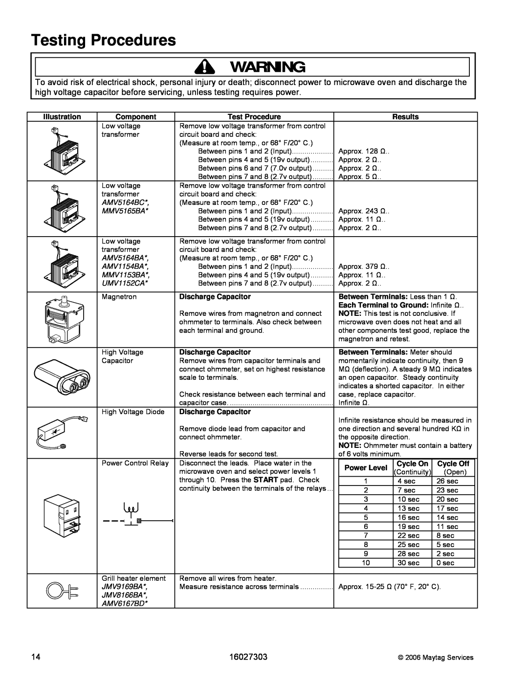
To avoid risk of electrical shock, personal injury or death; disconnect power to microwave oven and discharge the high voltage capacitor before servicing, unless testing requires power.
Illustration | Component | Test Procedure |
| Results |
|
| Low voltage | Remove low voltage transformer from control |
|
|
|
| transformer | circuit board and check: |
|
|
|
|
| (Measure at room temp., or 68° F/20° C.) | Approx. 128 Ω.. |
|
|
|
| Between pins 1 and 2 (Input) |
|
| |
|
| Between pins 4 and 5 (19v output) | Approx. 2 Ω.. |
|
|
|
| Between pins 6 and 7 (7.0v output) | Approx. 2 Ω.. |
|
|
|
| Between pins 7 and 8 (2.7v output) | Approx. 5 Ω.. |
|
|
| Low voltage | Remove low voltage transformer from control |
|
|
|
| transformer | circuit board and check: |
|
|
|
| AMV5164BC*, | (Measure at room temp., or 68° F/20° C.) | Approx. 243 Ω.. |
|
|
| MMV5165BA* | Between pins 1 and 2 (Input) |
|
| |
|
| Between pins 4 and 5 (19v output) | Approx. 11 Ω.. |
|
|
|
| Between pins 7 and 8 (2.7v output) | Approx. 2 Ω.. |
|
|
| Low voltage | Remove low voltage transformer from control |
|
|
|
| transformer | circuit board and check: |
|
|
|
| AMV5164BA*, | (Measure at room temp., or 68° F/20° C.) | Approx. 379 Ω.. |
|
|
| AMV1154BA*, | Between pins 1 and 2 (Input) |
|
| |
| MMV1153BA*, | Between pins 4 and 5 (19v output) | Approx. 11 Ω.. |
|
|
| UMV1152CA* | Between pins 7 and 8 (2.7v output) | Approx. 2 Ω.. |
|
|
| Magnetron | Discharge Capacitor | Between Terminals: Less than 1 Ω. | ||
|
|
| Each Terminal to Ground: Infinite Ω.. | ||
|
| Remove wires from magnetron and connect | NOTE: This test is not conclusive. If | ||
|
| ohmmeter to terminals. Also check between | microwave oven does not heat and all | ||
|
| each terminal and ground. | other components test good, replace the | ||
|
|
| magnetron and retest. |
| |
| High Voltage | Discharge Capacitor | Between Terminals: Meter should | ||
| Capacitor | Remove wires from capacitor terminals and | momentarily indicate continuity, then 9 | ||
|
| connect ohmmeter, set on highest resistance | MΩ (deflection). A steady 9 MΩ indicates | ||
|
| scale to terminals. | an open capacitor. Steady continuity | ||
|
|
| indicates a shorted capacitor. In either | ||
|
| Check resistance between each terminal and | case, replace capacitor. |
| |
|
| capacitor case | Infinite Ω. |
|
|
| High Voltage Diode | Discharge Capacitor | Infinite resistance should be measured in | ||
|
|
| |||
|
| Remove diode lead from capacitor and | one direction and several hundred KΩ in | ||
|
| connect ohmmeter. | the opposite direction. |
| |
|
|
| NOTE: Ohmmeter must contain a battery | ||
| Power Control Relay | Reverse leads for second test. | of 6 volts minimum. |
| |
| Disconnect the leads. Place water in the | Power Level | Cycle On | Cycle Off | |
|
| microwave oven and select power levels 1 | (Continuity) | (Open) | |
|
| through 10. Press the START pad. Check | 1 | 4 sec | 26 sec |
|
| continuity between the terminals of the relays ... | 2 | 7 sec | 23 sec |
|
|
| 3 | 10 sec | 20 sec |
|
|
| 4 | 13 sec | 17 sec |
|
|
| 5 | 16 sec | 14 sec |
|
|
| 6 | 19 sec | 11 sec |
|
|
| 7 | 22 sec | 8 sec |
|
|
| 8 | 25 sec | 5 sec |
|
|
| 9 | 28 sec | 2 sec |
|
|
| 10 | 30 sec | 0 sec |
| Grill heater element | Remove all wires from heater. |
|
|
|
| JMV9169BA*, | Measure resistance across terminals | Approx. | ||
| JMV8166BA*, |
|
|
|
|
| AMV6167BD* |
|
|
|
|
14 | 16027303 | © 2006 Maytag Services |