Disassembly Procedures
!WARNING
To avoid risk of electrical shock, personal injury or death; disconnect power to microwave oven and discharge the high voltage capacitor before performing any disassembly procedures.
Interlock Door Latch Switches Removal
Primary switch is operated by the top latch pawl.
Interlock Switch Removal
1.Disconnect power to oven and remove control panel, see "Control Panel Removal" procedure.
2.Discharge high voltage capacitor, see "High Voltage Capacitor Removal" procedure.
3.Test interlock switches before removing, see Testing Procedures.
4.Disconnect and label wire connections.
5.Remove interlock switch.
![]() Latch Board
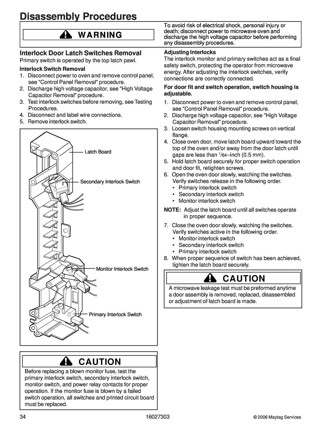
Latch Board
Secondary Interlock Switch
Monitor Interlock Switch
Primary Interlock Switch
Adjusting Interlocks
The interlock monitor and primary switches act as a final safety switch, protecting the operator from microwave energy. After adjusting the interlock switches, verify connections are correctly connected.
For door fit and switch operation, switch housing is adjustable.
1.Disconnect power to oven and remove control panel, see "Control Panel Removal" procedure.
2.Discharge high voltage capacitor, see "High Voltage Capacitor Removal" procedure.
3.Loosen switch housing mounting screws on vertical flange.
4.Close oven door, move latch board upward toward the top of the oven and/or away from the door latch until gaps are less than
5.Hold latch board securely for proper switch operation and door fit, retighten screws.
6.Open the oven door slowly, watching the switches. Verify switches release in the following order.
•Primary interlock switch
•Secondary interlock switch
•Monitor interlock switch
NOTE: Adjust the latch board until all switches operate in proper sequence.
7.Close the oven door slowly, watching the switches. Verify switches active in the following order.
•Monitor interlock switch
•Secondary interlock switch
•Primary interlock switch
8.When proper sequence of switch has been achieved, tighten the latch board securely.
!CAUTION
A microwave leakage test must be preformed anytime a door assembly is removed, replaced, disassembled or adjustment of latch board is made.
!CAUTION
Before replacing a blown monitor fuse, test the primary interlock switch, secondary interlock switch, monitor switch, and power relay contacts for proper operation. If the monitor fuse is blown by a failed switch operation, all switches and printed circuit board must be replaced.
34 | 16027303 |
© 2006 Maytag Services