Disassembly Procedures
!WARNING
To avoid risk of electrical shock, personal injury or death; disconnect power to microwave oven and discharge the high voltage capacitor before performing any disassembly procedures.
Control Key Panel Removal |
| |
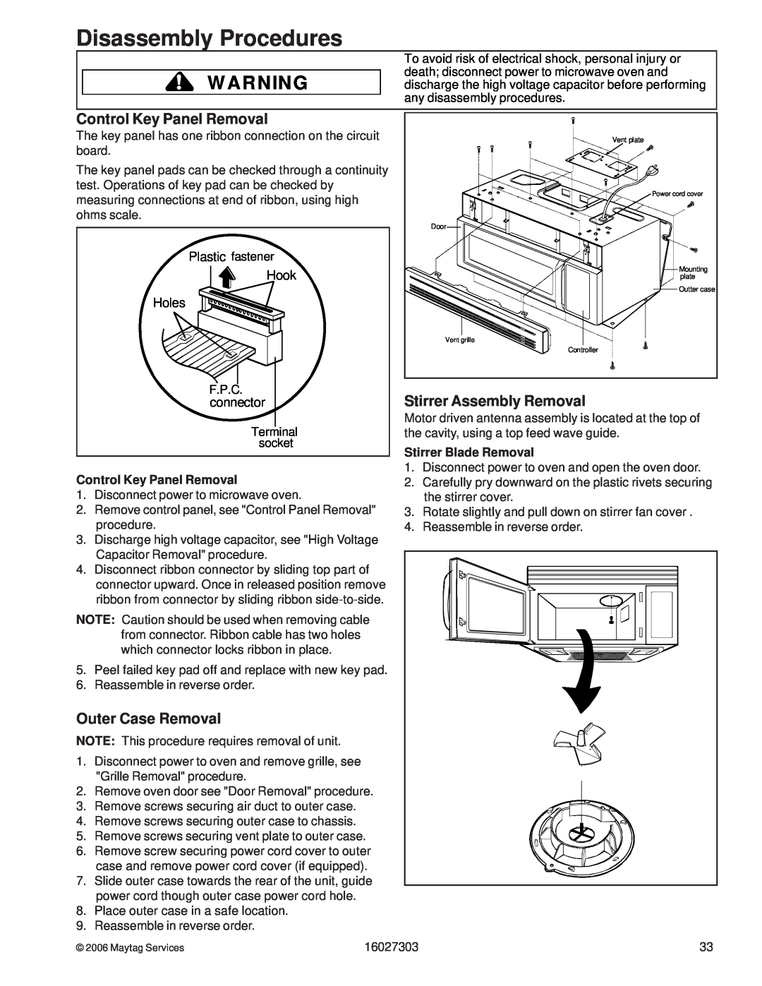
The key panel has one ribbon connection on the circuit | Vent plate | |
board. |
| |
The key panel pads can be checked through a continuity |
| |
test. Operations of key pad can be checked by | Power cord cover | |
measuring connections at end of ribbon, using high | ||
| ||
ohms scale. | Door | |
| ||
Plastic fastener | Mounting | |
Hook | ||
plate | ||
| Outter case |
Holes
Vent grille
|
|
|
| Controller |
| F.P.C. |
| Stirrer Assembly Removal | |
| connector |
| ||
| Terminal |
| Motor driven antenna assembly is located at the top of | |
|
| the cavity, using a top feed wave guide. | ||
| socket |
| Stirrer Blade Removal | |
|
|
| ||
Control Key Panel Removal |
| 1. Disconnect power to oven and open the oven door. | ||
| 2. Carefully pry downward on the plastic rivets securing | |||
1. | Disconnect power to microwave oven. |
|
| the stirrer cover. |
2. | Remove control panel, see "Control Panel Removal" | 3. Rotate slightly and pull down on stirrer fan cover . | ||
3. | procedure. |
| 4. | Reassemble in reverse order. |
Discharge high voltage capacitor, see "High Voltage |
|
| ||
| Capacitor Removal" procedure. |
|
|
|
4. | Disconnect ribbon connector by sliding top part of |
|
| |
| connector upward. Once in released position remove |
|
| |
| ribbon from connector by sliding ribbon |
|
| |
NOTE: Caution should be used when removing cable |
|
| ||
| from connector. Ribbon cable has two holes |
|
|
|
| which connector locks ribbon in place. |
|
|
|
5. | Peel failed key pad off and replace with new key pad. |
|
| |
6. | Reassemble in reverse order. |
|
|
|
Outer Case Removal |
|
|
| |
NOTE: This procedure requires removal of unit. |
|
|
| |
1. | Disconnect power to oven and remove grille, see |
|
|
|
| "Grille Removal" procedure. |
|
|
|
2. | Remove oven door see "Door Removal" procedure. |
|
| |
3. | Remove screws securing air duct to outer case. |
|
|
|
4. | Remove screws securing outer case to chassis. |
|
|
|
5. | Remove screws securing vent plate to outer case. |
|
| |
6. | Remove screw securing power cord cover to outer |
|
| |
| case and remove power cord cover (if equipped). |
|
| |
7. | Slide outer case towards the rear of the unit, guide |
|
| |
| power cord though outer case power cord hole. |
|
|
|
8. | Place outer case in a safe location. |
|
|
|
9. | Reassemble in reverse order. |
|
|
|
© 2006 Maytag Services | 16027303 | 33 | ||
