BASE MODEL CHARACTERISTICS
MS2421 Scanner
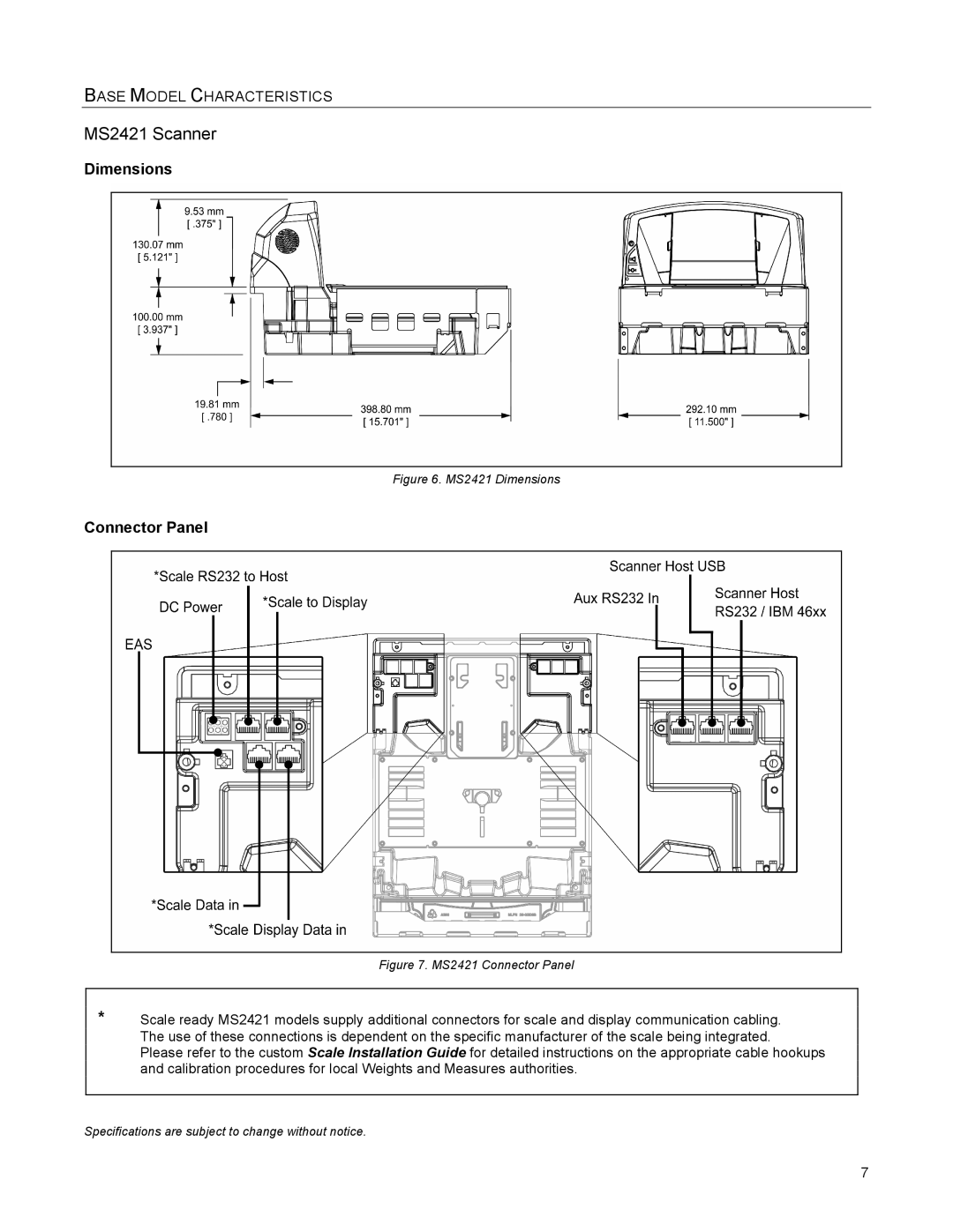
Dimensions
Figure 6. MS2421 Dimensions
Connector Panel
Figure 7. MS2421 Connector Panel
*Scale ready MS2421 models supply additional connectors for scale and display communication cabling. The use of these connections is dependent on the specific manufacturer of the scale being integrated.
Please refer to the custom Scale Installation Guide for detailed instructions on the appropriate cable hookups and calibration procedures for local Weights and Measures authorities.
Specifications are subject to change without notice.
7