Manuals
/
Meyer
/
Household Appliance
/
Vacuum Cleaner
Meyer
3216, 4218, 4220, 3220, 4216, 3218, 4222
manual
Adjustments, 25, 3200 & 4200 Series
Models:
4220
3218
4216
Front and Rear Unload Forage Boxes with Indpendent Outfeed Clutch
3220
4222
3216
4218
1
27
68
68
Download
68 pages
43.77 Kb
24
25
26
27
28
29
30
31
Troubleshooting
Specification
Repair Parts
Warranty
Maintenance
Complete Assembly, Key
Start Up Procedures
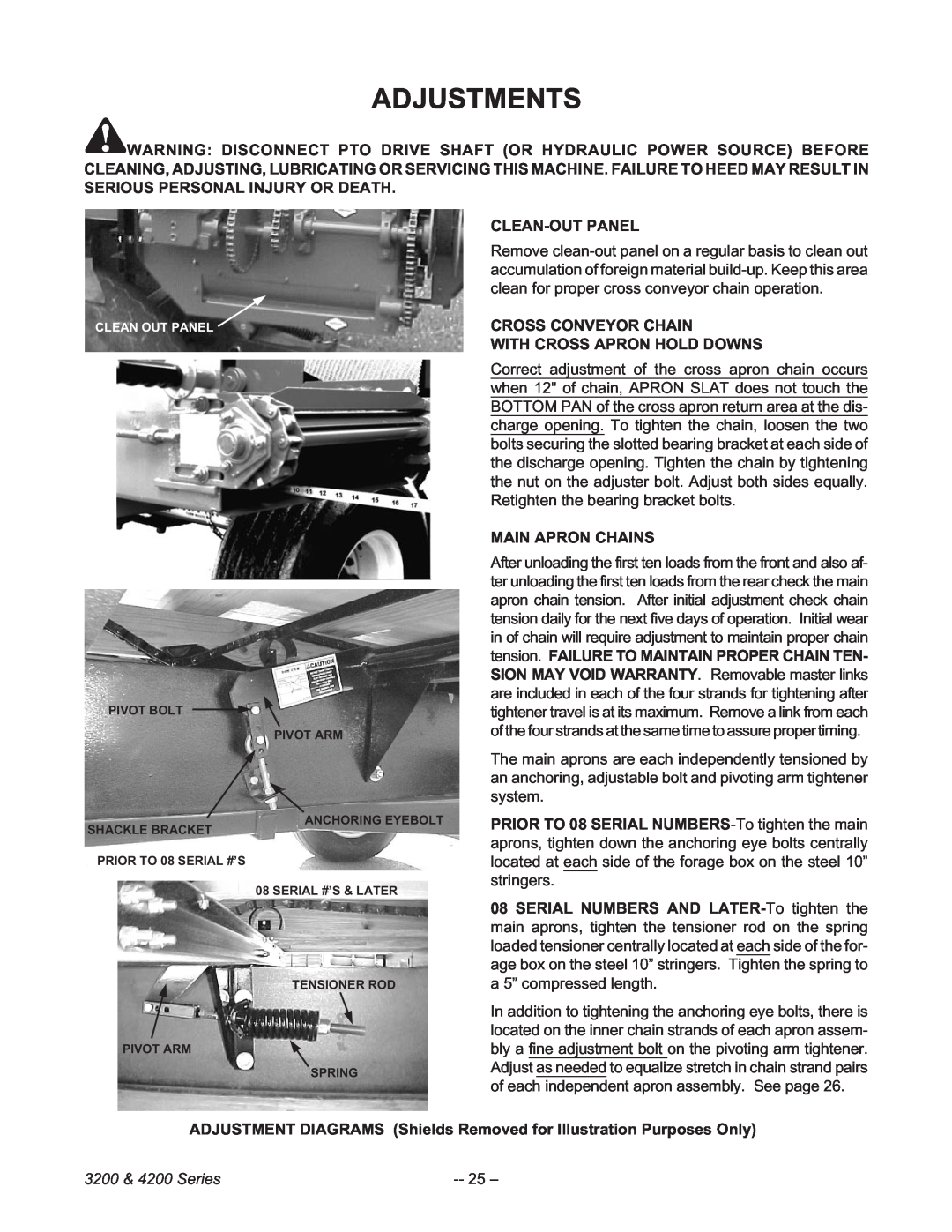
Adjustments
Resetting The Emergency Stop
Safety Precautions
Page 27
Image 27
Page 26
Page 28
Page 27
Image 27
Page 26
Page 28
Contents
4200 SERIES
TSS VARIABLE SPEED MODEL
Front & Rear Unload Forage Boxes
3200 SERIES
Page
3200 & 4200 Series
TABLE OF CONTENTS
3200 & 4200 Series
MANUFACTURER’S WARRANTY
NEW MEYER FRONT & REAR UNLOAD FORAGE BOX
3200 & 4200 Series
INTRODUCTION
FARM EQUIPMENT BUYERS TRUST THE NAME MEYER
3200 & 4200 Series
SAFETY PRECAUTIONS
Study the Above Safety Rules
3200 & 4200 Series
46-0001-5 46-0001-26 INSIDE COVER 46-0004-2
SAFETY FIRST
46-0001-14
46-0001-15
SAFETY FIRST
46-0001-4 46-0011 46-0001-20
3200 & 4200 Series
3200 & 4200 Series
RESETTING THE EMERGENCY STOP
OPERATION OF THE EMERGENCY STOP
EMERGENCY STOP TRIP LOCATIONS
3200 & 4200 Series
PRE-OPERATIONTRANSPORTING
10 –
PROPER PTO DRIVE SHAFT AND HYDRAULIC HOSE STORAGE
3200 & 4200 Series
STEP
FRONT UNLOAD DRIVE COUPLER “SET-UP”
PTO OR HYDRAULIC DRIVE
Truck Mount Forage Boxes
3200 & 4200 Series
#37-0010COUPLING PLATE ASSEMBLY COMPLETE
12 –
STEP
Shield Removed For Illustration Purposes Only
13 –
STEP
STEP IMPORTANT! MUST PERFORM
STEP
STEP 4a PTO DRIVE or
STEP 4b HYDRAULIC DRIVE
14 –
3200 & 4200 Series
OUTFEED CLUTCH
FORAGE BOX CONTROL LEVERS
15 –
OPERATOR TRAFFIC PATTERN
UNLOADING THE FORAGE BOX
16 –
START UP PROCEDURES
3200 & 4200 Series
17 –
SHUTDOWN PROCEDURES
REAR OPENING DISCHARGE DOOR CAUTION QUICK RELEASE
REAR DISCHARGE DOOR LATCH
REAR UNLOADOPERATION PTO OR HYDRAULIC DRIVE
18 –
REAR OPENING DISCHARGE DOOR
19 –
REAR OPENING DISCHARGE DOOR CAUTION QUICK RELEASE
3200 & 4200 Series
BEGINNING OF CROP MAINTENANCE
LUBRICATION
DAILY LUBRICATION
END OF CROP CLEANUP AND MAINTE- NANCE
21 –
3200 & 4200 Series
22 –
START UP PROCEDURES
TWO-SPEEDOPERATION
CONTROL LEVER
3200 & 4200 Series
23 –
ROLLER CHAIN DRIVES
TWO SPEED LUBRICATION AND MAINTENANCE
DAILY LUBRICATION MAINTENANCE
END OF CROP CLEANUP AND MAINTE NANCE
ADJUSTMENTS
25 –
3200 & 4200 Series
3200 & 4200 Series
ADJUSTMENT of 3200-4200SERIES MAIN APRON CHAINS
WARRANTY MAY BE VOIDED
26 –
08 SERIAL #’S & LATER
27 –
ADJUSTMENT of 3200-4200SERIES MAIN APRON CHAINS
WARRANTY MAY BE VOIDED
VARIABLE SPEED CONTROL ADJUSTMENT
28 –
RANGE CONTROL CLUTCH ADJUSTMENT
VARIABLE SPEED BELT REPLACEMENT
3200 & 4200 Series
INDEPENDENT OUTFEED CLUTCH BELT RE- PLACEMENT
INDEPENDENT OUTFEED CLUTCH ADJUSTMENT
tion Purposes Only
3200 & 4200 Series
This Page Intentionally Blank
REPAIR PARTS
3200-4200SERIES HYDRAULIC REAR UNLOAD COMPONENTS
3200 & 4200 Series
PTO REAR UNLOAD DRIVE TRAIN
32 –
3200 & 4200 Series
PART NO
PTO REAR UNLOAD DRIVE CLUTCH
33 –
TRUCK MOUNT ONLY
34 –
25-0215
3200 & 4200 Series
PART NO
TSS UNIT FRAME W/ IOC
35 –
3200 & 4200 Series
3200 & 4200 Series
TSS CROSS CONVEYOR W/IOC
FRONT & REAR UNLOAD MAIN APRON
37 –
3200 & 4200 Series
3200 & 4200 Series
TWO SPEED CLUSTER DRIVE
38 –
COMPLETE ASSEMBLY, KEY
3200 & 4200 Series
39 –
TWO SPEED CLUSTER DRIVE
17-0001
3200 & 4200 Series
TSS VARIABLE SPEED CLUSTER DRIVE W/IOC
40 –
COMPLETE ASSEMBLY, KEY
17-0001
TSS VARIABLE SPEED CLUSTER DRIVE W/IOC
3200 & 4200 Series
TSS AUGERS & AUGER DRIVE
3200 & 4200 Series
3200-4200SERIES INDEPENDENT OUTFEED CLUTCH DRIVE
“STOP” & “RUN” CONTROL RELATED PARTS
43 –
INDEPENDENT OUTFEED CLUTCH
44 –
3200 & 4200 Series
TWO SPEED HI-LOSHIFTER CONTROL
45 –
3200 & 4200 Series
UPPER GEAR BOX WITH INPUT SHAFT ASSEMBLY
46 –
3200 & 4200 Series
#19-0015 UPPER GEAR BOX WITH INPUT SHAFT ASSEMBLY
47 –
3200 & 4200 Series
3200 & 4200 Series
#19-0024 50:1 RATIO, FRONT, LOWER GEARBOX
48 –
3200 & 4200 SERIES
3200 & 4200 Series
#19-0032 1:1 RATIO, REAR GEARBOX PARALLEL SHAFT
49 –
3200 & 4200 SERIES
3200 & 4200 Series
#19-0025 25:1 RATIO, REAR GEARBOX
50 –
3200 & 4200 SERIES
#18-0117 UNIVERSAL JOINT TELESCOPING ASSEMBLY
51 –
3200 & 4200 Series
3200 & 4200 Series
12R UNIVERSAL JOINT TELESCOPING ASSEMBLY W/GUARD
#18-0017
52 –
#52-0003S STEEL STRINGER TIE DOWN KIT
53 –
3200 & 4200 Series
DESCRIPTION
#52-0001TK TSS 12 OPTIONAL EXTENSION KIT
54 –
Regular LH Unloading
#52-0019-PKG HIGHWAY LIGHT PACKAGE KIT
55 –
3200 & 4200 Series
3200 SERIES BOX PARTS
56 –
3200 & 4200 Series
PART NO
57 –
3200 SERIES BOX PARTS
3200 & 4200 Series
4200 SERIES BOX PARTS
58 –
3200 & 4200 Series
PART NO
59 –
4200 SERIES BOX PARTS
3200 & 4200 Series
GATE 3100/3200/4100/4200 BOX
GATE DELAY ADJUSTMENTS
3200 & 4200 Series
3200 & 4200 Series
OPTIONAL HYDRAULIC DRIVE
3200 & 4200 Series
“TROUBLE SHOOTING”
MEYER FRONT & REAR FORAGE BOXES
62 –
MODEL
“SPECIFICATIONS”
MEYER FRONT & REAR UNLOAD FORAGE BOXES
Meyer Mfg. Corp
3200 & 4200 Series
This Page Intentionally Blank
3200 & 4200 Series
This Page Intentionally Blank
Top
Page
Image
Contents