Mountings
3.Mount the grease cup holder to the rear flange hole with a ¼ - 20 x ¾" bolt and
When you complete the mount assembly go to the appropriate Grill Assembly Section and as- semble the grill head.
In-Ground Mounting
Assembly Instructions (MPP)
•Either the JNR or WNK model grills may be mounted on the
•The gas supply may be either LP or Natural.
•To protect against corrosion, you must apply a suitable coating on the post to retard the effects of corrosion existing in local areas.
•The grill head should not be attached to the post until the post is permanently cemented in ground.
Please check to be sure that all parts are included be- fore proceeding. Contact your dealer if any parts are missing.
Parts | Quantity |
4' Post | 1 |
Post access door | 1 |
28” Stainless Steel Tubing | 1 |
Stainless Steel Grease Cup | 1 |
Stainless Grease Cup Holder | 1 |
¼ - 20 x ¾" Hex Head Bolts | 3 |
¼ - 20 Kep Nuts | 3 |
Step 1: In-Ground Mounting Installation (Fig. 9)
1.Dig a posthole about 8 inches wide by 2 feet deep. Caution: Locate the hole so that the mounted grill head has a clearance of 24 inches away from any combustible object or surface; above, back, left or right.
Center the post in the hole and plumb it. Pour in
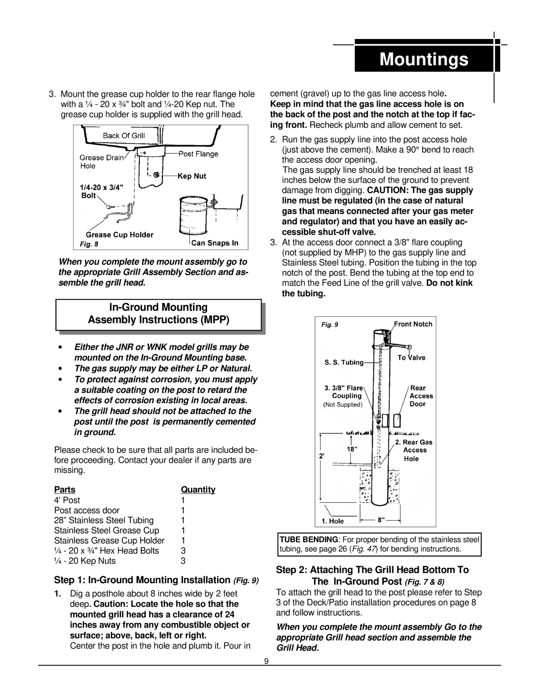
cement (gravel) up to the gas line access hole.
Keep in mind that the gas line access hole is on the back of the post and the notch at the top if fac- ing front. Recheck plumb and allow cement to set.
2.Run the gas supply line into the post access hole (just above the cement). Make a 90° bend to reach the access door opening.
The gas supply line should be trenched at least 18 inches below the surface of the ground to prevent damage from digging. CAUTION: The gas supply line must be regulated (in the case of natural gas that means connected after your gas meter and regulator) and that you have an easily ac- cessible
3.At the access door connect a 3/8" flare coupling (not supplied by MHP) to the gas supply line and Stainless Steel tubing. Position the tubing in the top notch of the post. Bend the tubing at the top end to match the Feed Line of the grill valve. Do not kink the tubing.
TUBE BENDING: For proper bending of the stainless steel tubing, see page 26 (Fig. 47) for bending instructions.
Step 2: Attaching The Grill Head Bottom To The In-Ground Post (Fig. 7 & 8)
To attach the grill head to the post please refer to Step 3 of the Deck/Patio installation procedures on page 8 and follow instructions.
When you complete the mount assembly Go to the appropriate Grill head section and assemble the Grill Head.
9