Chapter 2 Tour of Product
2.1USB Adapter
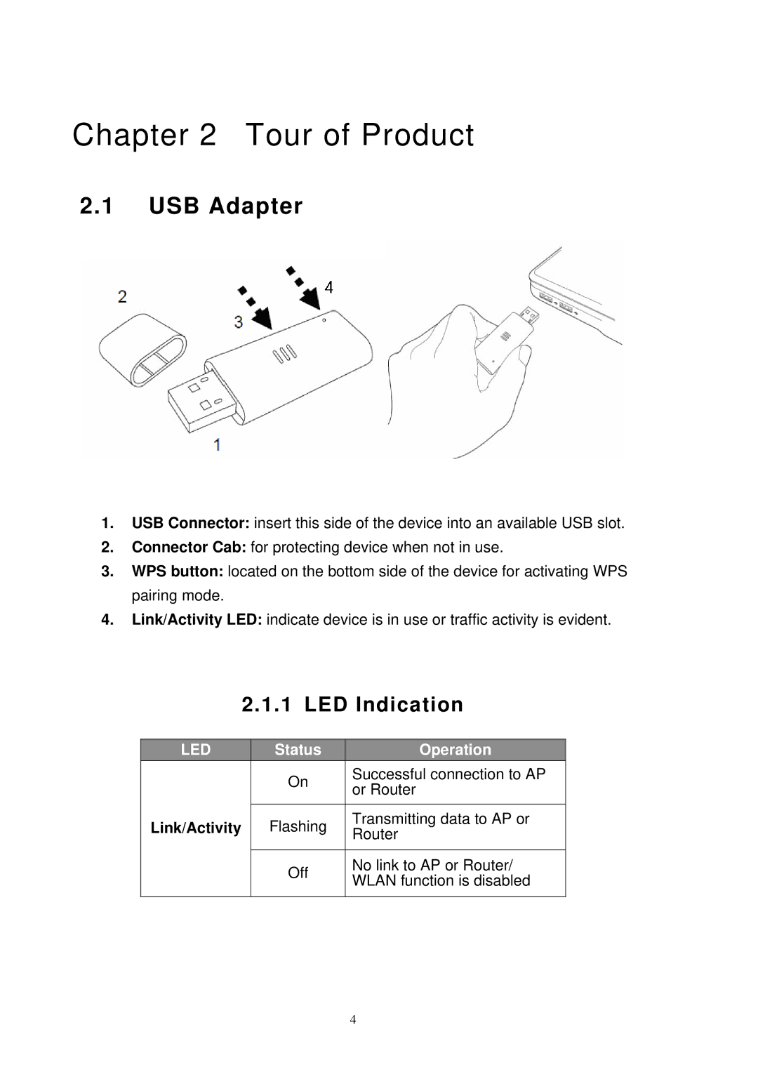
1.USB Connector: insert this side of the device into an available USB slot.
2.Connector Cab: for protecting device when not in use.
3.WPS button: located on the bottom side of the device for activating WPS pairing mode.
4.Link/Activity LED: indicate device is in use or traffic activity is evident.
2.1.1LED Indication
| LED |
| Status |
| Operation |
|
|
| On |
| Successful connection to AP |
|
|
|
| or Router | |
|
|
|
|
| |
|
|
|
|
|
|
| Link/Activity |
| Flashing |
| Transmitting data to AP or |
|
|
| Router | ||
|
|
|
|
| |
|
|
|
|
|
|
|
|
| Off |
| No link to AP or Router/ |
|
|
|
| WLAN function is disabled | |
|
|
|
|
| |
|
|
|
|
|
|
4