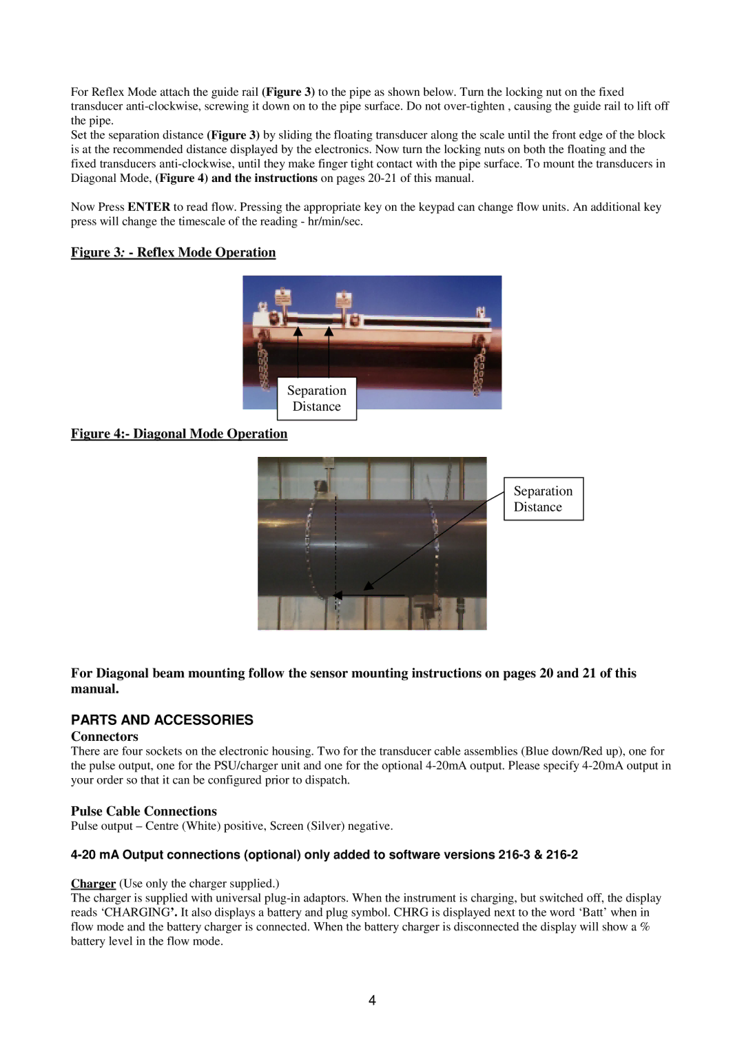
For Reflex Mode attach the guide rail (Figure 3) to the pipe as shown below. Turn the locking nut on the fixed transducer
Set the separation distance (Figure 3) by sliding the floating transducer along the scale until the front edge of the block is at the recommended distance displayed by the electronics. Now turn the locking nuts on both the floating and the fixed transducers
Now Press ENTER to read flow. Pressing the appropriate key on the keypad can change flow units. An additional key press will change the timescale of the reading - hr/min/sec.
Figure 3: - Reflex Mode Operation
Separation
Distance
Figure 4:- Diagonal Mode Operation
Separation
Distance
For Diagonal beam mounting follow the sensor mounting instructions on pages 20 and 21 of this manual.
PARTS AND ACCESSORIES
Connectors
There are four sockets on the electronic housing. Two for the transducer cable assemblies (Blue down/Red up), one for the pulse output, one for the PSU/charger unit and one for the optional
Pulse Cable Connections
Pulse output – Centre (White) positive, Screen (Silver) negative.
Charger (Use only the charger supplied.)
The charger is supplied with universal
4