2007 Miele USA
TECHNICAL INFORMATION CVA615 Coffee System
CVA615 Coffee System – Table of Contents
Service and Maintenance
Fault Diagnosis
CVA615 Coffee System – List of Figures
CVA615 Coffee System – List of Figures continued
Figure 5-43:Beans Container Guide
Table 6-2:Service Mode Navigation
CVA615 Coffee System – List of Tables
CVA615 Coffee System
Technical Information
1.1Appliance Overview
1.0Construction and Design
2Coffee Dispensers Height-Adjustable
1Hot Water Dispenser
1.1.2Controls
1.1.3Interior Front of Appliance Opened
Figure 1-2: CVA Controls
1.2Technical Data
Product Dimensions
Electrical Information
6Drive Assembly Mounted to Wall
1.3Layout of Components
7Drive Assembly Cover 8Hot Water / Coffee Heater
12Steam Solenoid Valve 13Power Electronic Board
Figure 2-1: Operating Manual
2.0Installation
3.1General Operation
3.0Commission and Operation
Figure 3-4: Canceling the Preparation Process
3.1.2Canceling the Preparation
3.1.3Steam Control
Figure 3-5: Steam Selector
3.1.4Hot Water
Controls
3.1.5Adjusting the Coffee Grinder
3.1.6Filling the Coffee Beans Container
3.1.7Filling the Water Tank
4.1Door Switch
4.2Overflow Reed Switch
4.0Description of Function
4.3Brew Unit – Cleaning and Care
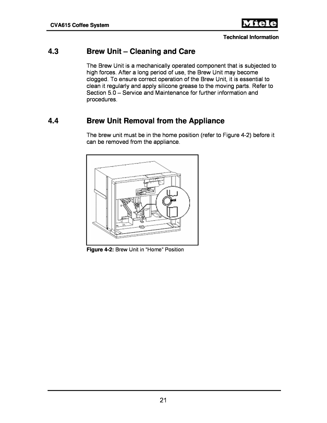
4.4Brew Unit Removal from the Appliance
Figure 4-2: Brew Unit in “Home” Position
Operation
4.5Connection of Brew Unit to Drive Mechanism
4.6Brewing Procedure
Figure 4-5: Brew Unit Components
1Outlet 2Top Filter 3Compressed Coffee
4Water Nozzle Socket 5Bottom Filter
Refer to Figure 4-6– Brew Unit, Showing Compressed Coffee “Puck”
4.8Waste Unit Present Switch
4.7Grounds Container
Figure 4-7: Waste Unit Present Switch
Figure 4-8: Waste Unit
1 Magnet for Present Switch Actuation
4.9Water Tank
4.10Water Level Switch
Figure 4-10: Water Level Switch
Figure 4-11: Water Level Switch Float
When the water tank is installed, and contains at least 30-33ounces of water; the Water Level Switch is activated and its contacts close
Figure 4-12: Grinder Assembly
4.11Grinder Assembly
Refer to Figure 4-12– Grinder Assembly
4.12Grinder – Overload Protection
1Grinder Motor 2Carrier 3Mounting 4Spring 5Ball
6Grinding Cone 7Washer 8Intake Worm Gear
CForce Transfer Interrupted
ANormal Operation BOverload Protection Activated
Figure 4-15: Coffee Dispensing Components
4.13Ground Coffee Dispensing
4.14Dispenser Switch
3Locking Mechanism Switch Lug
4.15Brew Unit Drives
4Switch – Brew Unit Present Switch
1Brew Unit Drive Shaft Socket 2Socket
Refer to Figure 4-18– Brew Unit Drive Assembly
4.17Flow Meter
4.16Water Pump
4.18Heaters
Coffee / Hot Water Heater 1R1 & 1R2
Figure 4-19: Hot Water / Coffee Heater
4.19Flow Through Heaters
Figure 4-20: Steam Heater
1Heater Element 2Thermal Fuse 3Thermostat
4Temperature Sensor PTC
Figure 4-21: Water Path
4.20Water Path
4.20.2Water Path - Coffee
4.20.1Water Intake
4.20.3Water Path – Hot Water
4.20.4Water Path – Steam
Figure 4-22: Water Valve Disassembled
4.21Water Valve
4.22.1Power Electronic
4.22Electronic Assemblies
Figure 4-24: CPU Control Electronic
4.22.2CPU Electronic
5.1Lid - Removal
5.0Service and Maintenance
5.3Rear Panel - Removal
5.2Interference Suppression Filter Z1 - Removal
5.4Adjustment Slide Switch Frame - Removal
1.Open the door 2.Pull off the slide switch knobs
4.Remove the frame
Refer to Figure 5-5– Door Switch
5.5Door Contact Switch S24 - Removal
3.Disconnect the Door Switch Connections
5.Remove the Door Switch to the front