2007 Miele USA
TECHNICAL INFORMATION CVA615 Coffee System
CVA615 Coffee System – Table of Contents
Service and Maintenance
Fault Diagnosis
CVA615 Coffee System – List of Figures
CVA615 Coffee System – List of Figures continued
Figure 5-43:Beans Container Guide
Technical Information
CVA615 Coffee System – List of Tables
Table 6-2:Service Mode Navigation
CVA615 Coffee System
1Hot Water Dispenser
1.0Construction and Design
1.1Appliance Overview
2Coffee Dispensers Height-Adjustable
Figure 1-2: CVA Controls
1.1.2Controls
1.1.3Interior Front of Appliance Opened
Electrical Information
1.2Technical Data
Product Dimensions
12Steam Solenoid Valve 13Power Electronic Board
1.3Layout of Components
6Drive Assembly Mounted to Wall
7Drive Assembly Cover 8Hot Water / Coffee Heater
Figure 2-1: Operating Manual
2.0Installation
3.1General Operation
3.0Commission and Operation
Figure 3-5: Steam Selector
3.1.2Canceling the Preparation
Figure 3-4: Canceling the Preparation Process
3.1.3Steam Control
3.1.4Hot Water
Controls
3.1.5Adjusting the Coffee Grinder
3.1.6Filling the Coffee Beans Container
3.1.7Filling the Water Tank
4.0Description of Function
4.1Door Switch
4.2Overflow Reed Switch
Figure 4-2: Brew Unit in “Home” Position
4.3Brew Unit – Cleaning and Care
4.4Brew Unit Removal from the Appliance
Operation
4.5Connection of Brew Unit to Drive Mechanism
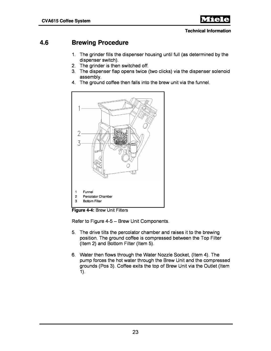
4.6Brewing Procedure
4Water Nozzle Socket 5Bottom Filter
Figure 4-5: Brew Unit Components
1Outlet 2Top Filter 3Compressed Coffee
Refer to Figure 4-6– Brew Unit, Showing Compressed Coffee “Puck”
Figure 4-7: Waste Unit Present Switch
4.8Waste Unit Present Switch
4.7Grounds Container
Figure 4-8: Waste Unit
1 Magnet for Present Switch Actuation
4.9Water Tank
Figure 4-11: Water Level Switch Float
4.10Water Level Switch
Figure 4-10: Water Level Switch
When the water tank is installed, and contains at least 30-33ounces of water; the Water Level Switch is activated and its contacts close
Figure 4-12: Grinder Assembly
4.11Grinder Assembly
Refer to Figure 4-12– Grinder Assembly
6Grinding Cone 7Washer 8Intake Worm Gear
4.12Grinder – Overload Protection
1Grinder Motor 2Carrier 3Mounting 4Spring 5Ball
CForce Transfer Interrupted
ANormal Operation BOverload Protection Activated
Figure 4-15: Coffee Dispensing Components
4.13Ground Coffee Dispensing
4.14Dispenser Switch
1Brew Unit Drive Shaft Socket 2Socket
4.15Brew Unit Drives
3Locking Mechanism Switch Lug
4Switch – Brew Unit Present Switch
Refer to Figure 4-18– Brew Unit Drive Assembly
Coffee / Hot Water Heater 1R1 & 1R2
4.16Water Pump
4.17Flow Meter
4.18Heaters
Figure 4-19: Hot Water / Coffee Heater
4.19Flow Through Heaters
4Temperature Sensor PTC
Figure 4-20: Steam Heater
1Heater Element 2Thermal Fuse 3Thermostat
Figure 4-21: Water Path
4.20Water Path
4.20.4Water Path – Steam
4.20.1Water Intake
4.20.2Water Path - Coffee
4.20.3Water Path – Hot Water
Figure 4-22: Water Valve Disassembled
4.21Water Valve
4.22.1Power Electronic
4.22Electronic Assemblies
Figure 4-24: CPU Control Electronic
4.22.2CPU Electronic
5.1Lid - Removal
5.0Service and Maintenance
5.3Rear Panel - Removal
5.2Interference Suppression Filter Z1 - Removal
4.Remove the frame
5.4Adjustment Slide Switch Frame - Removal
1.Open the door 2.Pull off the slide switch knobs
5.Remove the Door Switch to the front
5.5Door Contact Switch S24 - Removal
Refer to Figure 5-5– Door Switch
3.Disconnect the Door Switch Connections