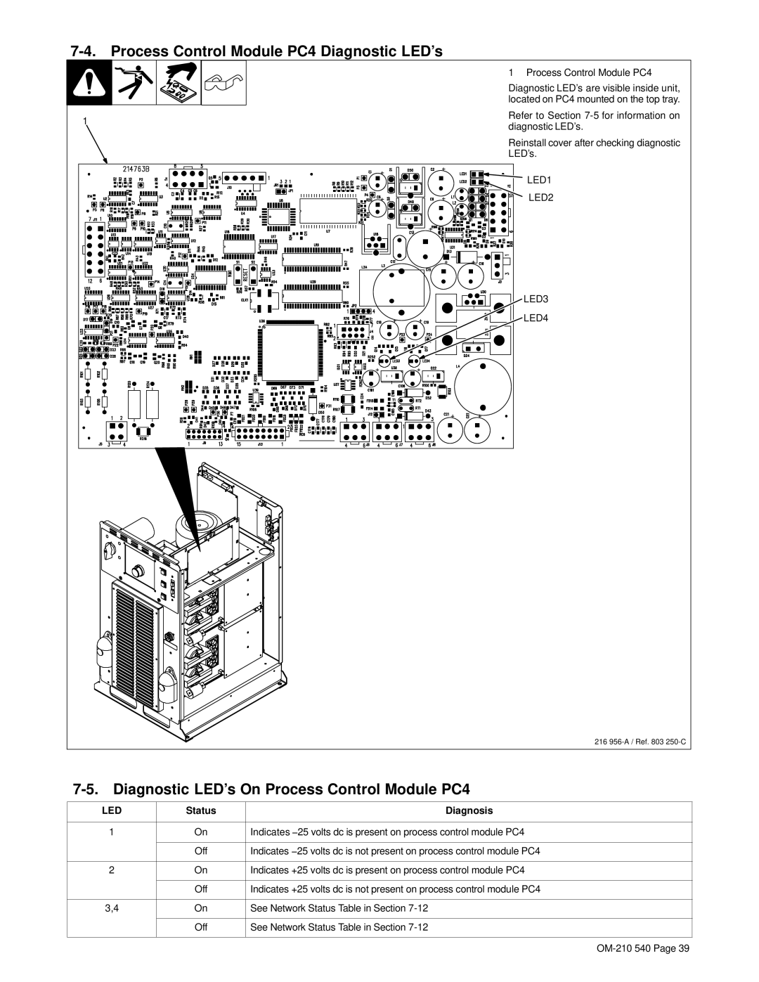
7-4. Process Control Module PC4 Diagnostic LED’s
1
1 Process Control Module PC4
Diagnostic LED’s are visible inside unit, located on PC4 mounted on the top tray.
Refer to Section
Reinstall cover after checking diagnostic LED’s.
LED1
LED2
LED3
LED4
216
7-5. Diagnostic LED’s On Process Control Module PC4
LED | Status | Diagnosis |
|
|
|
1 | On | Indicates −25 volts dc is present on process control module PC4 |
|
|
|
| Off | Indicates −25 volts dc is not present on process control module PC4 |
|
|
|
2 | On | Indicates +25 volts dc is present on process control module PC4 |
|
|
|
| Off | Indicates +25 volts dc is not present on process control module PC4 |
|
|
|
3,4 | On | See Network Status Table in Section |
|
|
|
| Off | See Network Status Table in Section |
|
|
|