Description
OM-4406
Processes
From Miller to You
Table of Contents
− Maintenance & Troubleshooting
Deccon111/02
Directives
Standards
Deccon1sound11/02
Sound Level Information
Arc Welding Hazards
Symbol Usage
Engine Hazards
Compressed Air Hazards
California Proposition 65 Warnings
Principal Safety Standards
EMF Information
Radiation can cause interference
− Consignes DE Sécurité − Lire Avant Utilisation
Signification des symboles
UN Choc Électrique peut tuer
LES Fumées ET LES GAZ peuvent être dangereux
DES Particules Volantes peuvent blesser les yeux
LE Soudage peut provoquer un in- cendie ou une explosion
DES Pièces Chaudes peuvent provoquer des brûlures graves
LE Bruit peut affecter l’ouïe
DES Organes Mobiles peuvent provoquer des blessures
’EXPLOSION DE LA Batterie peut
LA Chaleur DU Moteur peut pro- voquer un incendie
’AIR Comprimé peut provoquer des blessures
Information sur les champs électromagnétiques
Principales normes de sécurité
− Definitions
Starting Instructions
+ −
Can cause severe burns. Do
Are possible hazards as
Falling equipment can cause
Serious injury and damage
Return To Table Of Contents
− 50 h Std
Manufacturer’s Rating Labels For CE Products
Std
CC Models CC/CV Models
Symbols And Definitions
Dimensions, Weights, And Operating Angles
− Specifications
Weld, Power, And Engine Specifications
Volt-Ampere Curves For CC Models
MIG Mode
Stick Mode
TIG Mode
Volt-Ampere Curves For CC/CV Models
Duty Cycle And Overheating
Fuel Consumption
Optional Three-Phase Generator Curves
AC Generator Power Curve
12 kVA/kW Single-Phase AC Output No Weld Load
15 kVA/kW Three-Phase AC Output No Weld Load
Volt-Ampere Curve For CC/CV Models In AC TIG Mode
Installing Welding Generator See Sections 5-2And
− Installation
Location Grounding
Airflow Clearance
Using Lifting Eye
Supporting The Unit
Mounting Welding Generator
Mounting Surface
To Bolt Unit In Place
Tools Needed 1/2
Installing Exhaust Pipe
Stop engine and let cool
Point exhaust pipe in desired di
Do not overfill battery cells
Activating The Dry Charge Battery If Applicable
Read and follow all instruc
Charger
Connect Negative − Cable Last
Connecting The Battery
Reinstall cover after connecting battery
Engine Prestart Checks
Coolant Recovery Tank
Selecting Weld Cable Sizes
Connecting To Weld Output Terminals
Socket
Connecting To Remote 14 Receptacle RC14 On CC/CV Models
Front Panel Controls For CC Models See Section
− Operating Welding Generator − CC Models
Do not switch under load
Engine Indicator Lights
Engine Starting Controls
To Start Do not use ether
Weld Control/Arc Condition Information Label
Remote Amperage Control On CC Models Optional
Example
Set weld controls as shown to
Return To Table Of Contents
Front Panel Controls For CC/CV Models See Section
− Operating Welding Generator − CC/CV Models
Engine Oil Pressure Light
Use switch to select weld amperage range
Voltage/Amperage Adjust Switch And Remote 14 Receptacle
Process/Contactor Switch Settings
Process/Contactor Switch On CC/CV Models
Example Combination Remote Amperage Control TIG
Remote Voltage/Amperage Control On CC/CV Models Optional
Example Combination Remote Amperage Control Stick
Volt And 240 Volt Receptacles
− Operating Auxiliary Equipment
At least once a month, run en
Open, contact Factory Autho
Close panel opening if no connections are made to generator
Three-Phase Power Connection
Rear Of Panel
Circuit Breaker CB2 Circuit Breaker CB3
Optional Generator Power Receptacles
240 V 15 a AC South African Receptacle RC1
Maintenance Label
− Maintenance & Troubleshooting
Every 8 h
Routine Maintenance
Every 50 h
Every 100 h
Every 1000 h
Service
Every 2000 h
Caterpillar Customer Assistance
By the warranty
Servicing Air Cleaner
To clean air filter
Do not clean housing with air hose
Tools Needed 3/8
Inspecting And Cleaning Optional Spark Arrestor Muffler
Stop engine and let cool. Reinstall cleanout plug
Idle Speed Adjustment
Adjusting Engine Speed
Weld/Power Speed Adjustment
Engine Speed No Load
Servicing Fuel And Lubrication Systems
Overload Protection
Pre-Start Diagnostic Checks
Diagnosing Causes Of Engine Fault Shutdowns
Diagnostic Checks While Running
Start Engine With No Load Applied
Welding − CC Models
Troubleshooting
Welding − CC/CV Models
Engine
Standard Generator Power
Optional Three-Phase Generator Power CC/CV Models
Shutdown switch is released Out
Wiring harness and components
Temperature is too high see Sections 5-7and
Air in fuel system. See engine manual
Circuit Diagram For CC Welding Generator
− Electrical Diagrams
215 296-B
Circuit Diagram For CC/CV Welding Generator
215 297-B
Welding Generator
− RUN-IN Procedure
Wetstacking
Procedure at less than
Run-In Procedure Using Load Bank
Stop engine Do not touch hot exhaust
From flammables Do not Perform
Bank/grid
Run-In Procedure Using Resistance Grid
From flammables
Do not perform run-in
Has this symbol
− Generator Power Guidelines
Selecting Equipment
Grounding Generator To Truck Or Trailer Frame
How Much Power Does Equipment Require?
Grounding When Supplying Building Systems
Earth ground if supplying
Use ground device as stated Electrical codes
Approximate Power Requirements For Farm/Home Equipment
Approximate Power Requirements For Industrial Motors
Industrial Motors Rating Starting Watts Running Watts
Farm/Home Equipment Rating Starting Watts Running Watts
Contractor Rating Starting Watts Running Watts
Approximate Power Requirements For Contractor Equipment
How Much Power Can Generator Supply?
Power Required To Start Motor
Single-Phase Induction Motor Starting Requirements
KVA/HP x HP x 1000 = Starting Amperage
Typical Connections To Supply Standby Power
Current Load Watts Amperes
Selecting Extension Cord Use Shortest Cord Possible
113 108 100 CC only 119 110 109 111 -4 or
− Parts List
117 116 103 102 115 FIG 114 105 104 101 120
85 Fig
51 52
Dia Part Description Quantity
Dia Part Description Quantity Mkgs
095
Control Box Assembly − CC Models
Control Box Assembly − CC/CV Models
Control Box Assembly − CC/CV Models -1Item
Panel, Front w/Components − CC Models
MS1
Panel, Front w/Components − CC/CV Models -1Item
Panel, Front w/Components − CC/CV Models
PC6 192
PLG6
34 36 27 26
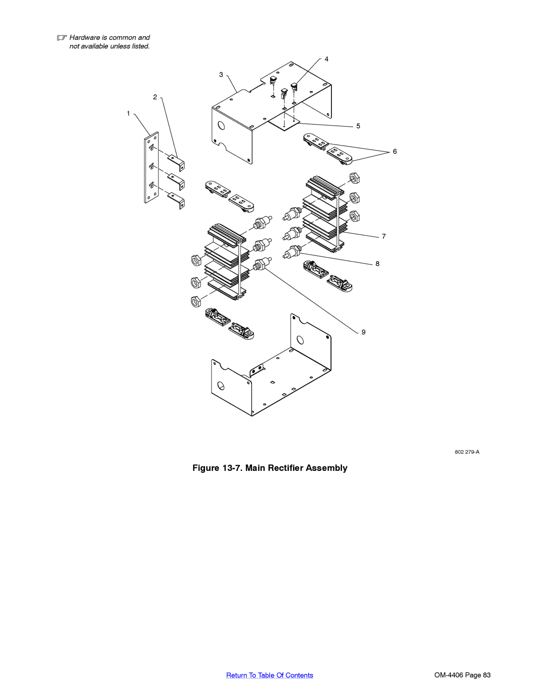
Hardware is common Not available unless listed
Main Rectifier Assembly -1Item
Main Rectifier Assembly
Page
Support
Your distributor also gives
For assistance in filing or settling claims, contact
Miller Electric Mfg. Co
Your distributor and/or equipment manufacturer’s
Transportation Department