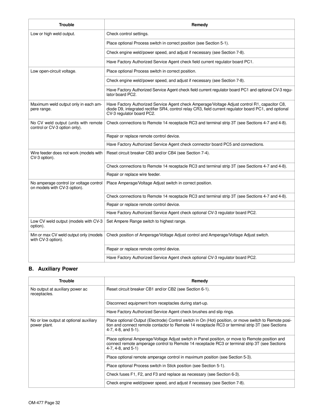
Trouble | Remedy |
|
|
Low or high weld output. | Check control settings. |
|
|
| Place optional Process switch in correct position (see Section |
|
|
| Check engine weld/power speed, and adjust if necessary (see Section |
|
|
| Have Factory Authorized Service Agent check field current regulator board PC1. |
|
|
Low | Place optional Process switch in correct position. |
|
|
| Check engine weld/power speed, and adjust if necessary (see Section |
|
|
| Have Factory Authorized Service Agent check field current regulator board PC1 and optional |
| lator board PC2. |
|
|
Maximum weld output only in each am- | Have Factory Authorized Service Agent check Amperage/Voltage Adjust control R1, capacitor C8, |
pere range. | diode D9, integrated rectifier SR4, control relay CR3, field current regulator board PC1, and optional |
| |
|
|
No CV weld output (units with remote | Check connections to Remote 14 receptacle RC3 and terminal strip 3T (see Sections |
control or |
|
|
|
| Repair or replace remote control device. |
|
|
| Have Factory Authorized Service Agent check connector board PC5 and connections. |
|
|
Wire feeder does not work (models with | Reset circuit breaker CB3 and/or CB4 (see Section |
| |
|
|
| Check connections to Remote 14 receptacle RC3 and terminal strip 3T (see Sections |
|
|
| Repair or replace wire feeder. |
|
|
No amperage control (or voltage control | Place Amperage/Voltage Adjust switch in correct position. |
on models with |
|
|
|
| Check connections to Remote 14 receptacle RC3 and terminal strip 3T (see Sections |
|
|
| Repair or replace remote control device. |
|
|
| Have Factory Authorized Service Agent check optional |
|
|
Low CV weld output (models with | Set Ampere Range switch to highest range. |
option). |
|
|
|
Min or max CV weld output only (models | Check position of Amperage/Voltage Adjust control and Amperage/Voltage Adjust switch. |
with |
|
|
|
| Repair or replace remote control device. |
|
|
| Have Factory Authorized Service Agent check optional |
|
|
B. Auxiliary Power |
|
Trouble | Remedy |
|
|
No output at auxiliary power ac | Reset circuit breaker CB1 and/or CB2 (see Section |
receptacles. |
|
|
|
| Disconnect equipment from receptacles during |
|
|
| Have Factory Authorized Service Agent check brushes and slip rings. |
|
|
No or low output at optional auxiliary | Place optional Output (Electrode) Control switch in On (Hot) position, or move switch to Remote posi- |
power plant. | tion and connect remote contactor to Remote 14 receptacle RC3 or terminal strip 3T (see Sections |
|
|
|
|
| Place optional Amperage/Voltage Adjust switch in Panel position, or move to Remote position and |
| connect remote amperage control to Remote 14 receptacle RC3 or terminal strip 3T (see Sections |
| |
|
|
| Place optional remote amperage control in maximum position (see Section |
|
|
| Place optional Process switch in Stick position (see Section |
|
|
| Check fuses F1, F2, and F3 and replace as necessary (see Section |
|
|
| Check engine weld/power speed, and adjust if necessary (see Section |
|
|