MGE Galaxy 5000
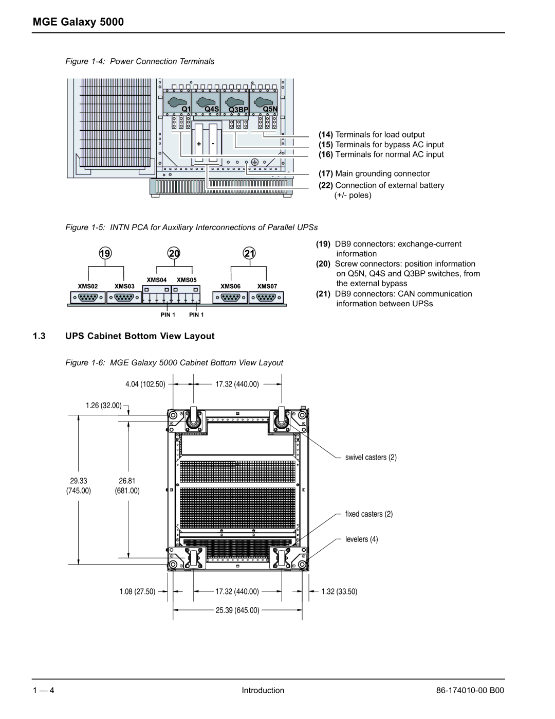
Figure 1-4: Power Connection Terminals
(14) Terminals for load output
(15) Terminals for bypass AC input
(16) Terminals for normal AC input
(17) Main grounding connector
(22) Connection of external battery (+/- poles)
Figure 1-5: INTN PCA for Auxiliary Interconnections of Parallel UPSs
(19) DB9 connectors:
(20) Screw connectors: position information on Q5N, Q4S and Q3BP switches, from the external bypass
(21) DB9 connectors: CAN communication information between UPSs
PIN 1 | PIN 1 |
1.3UPS Cabinet Bottom View Layout
Figure 1-6: MGE Galaxy 5000 Cabinet Bottom View Layout
4.04 (102.50) | 17.32 (440.00) |
1.26 (32.00)
swivel casters (2)
29.3326.81
(745.00) (681.00)
fixed casters (2)
levelers (4)
1.08 (27.50) | 17.32 (440.00) | 1.32 (33.50) |
| 25.39 (645.00) |
|
1 — 4 | Introduction |