Installation and User Manual
2.8Connection of the Relay Communications Card
CAUTION Isolate and
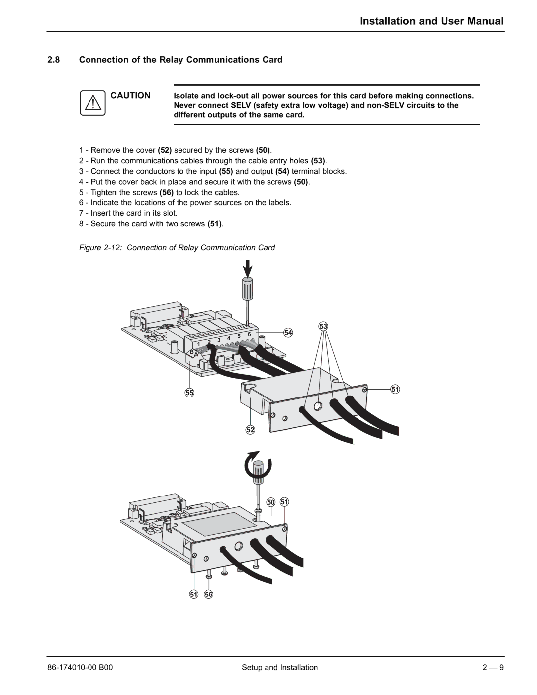
1 - Remove the cover (52) secured by the screws (50).
2 - Run the communications cables through the cable entry holes (53).
3 - Connect the conductors to the input (55) and output (54) terminal blocks. 4 - Put the cover back in place and secure it with the screws (50).
5 - Tighten the screws (56) to lock the cables.
6 - Indicate the locations of the power sources on the labels.
7 - Insert the card in its slot.
8 - Secure the card with two screws (51).
Figure 2-12: Connection of Relay Communication Card
Setup and Installation | 2 — 9 |