MGE Galaxy 5000
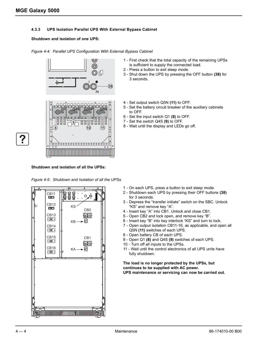
4.3.3UPS Isolation Parallel UPS With External Bypass Cabinet Shutdown and isolation of one UPS:
Figure 4-4: Parallel UPS Configuration With External Bypass Cabinet
1 - First check that the total capacity of the remaining UPSs is sufficient to supply the connected load.
2 - Press a button to exit sleep mode.
3 - Shut down the UPS by pressing the OFF button (38) for 3 seconds.
4 - Set output switch Q5N (11) to OFF.
5 - Set the battery circuit breaker of the auxiliary cabinets to OFF.
6 - Set the input switch Q1 (8) to OFF.
7 - Set the switch Q4S (9) to OFF.
8 - Wait until the display and LEDs go off.
Shutdown and isolation of all the UPSs:
Figure 4-5: Shutdown and Isolation of all the UPSs
CB11 |
1 - On each UPS, press a button to exit sleep mode.
2 - Shutdown each UPS by pressing their OFF buttons (38) for 3 seconds.
CB12
CB13
CB14
KS
CB2
KB ![]()
![]()
![]()
3 - Depress the “transfer initiate” switch on the SBC. Unlock “KS” and remove key “A”.
4 - Insert key “A” into CB1. Unlock and close CB1.
5 - Open CB2 and lock open, and remove key “B”.
6 - Insert key “B” into key interlock “KS” and turn to lock.
7 - Open output isolation
CB15CB1
CB16 | KA |
|
8 - Open battery CB of each UPS.
9 - Open Q1 (8) and Q4S (9) switches of each UPS.
10 - Turn off all inputs to the UPSs.
11 - Wait until the control electronics of all UPS units have fully shutdown.
The load is no longer protected by the UPSs, but continues to be supplied with AC power.
UPS maintenance or servicing can now be carried out.
4 — 4 | Maintenance |
