Installation and User Manual
CAUTION Only an authorized electrical professional should access electrical connections. A severe shock hazard exists.
2.3Connection of Power Cables in a Single UPS
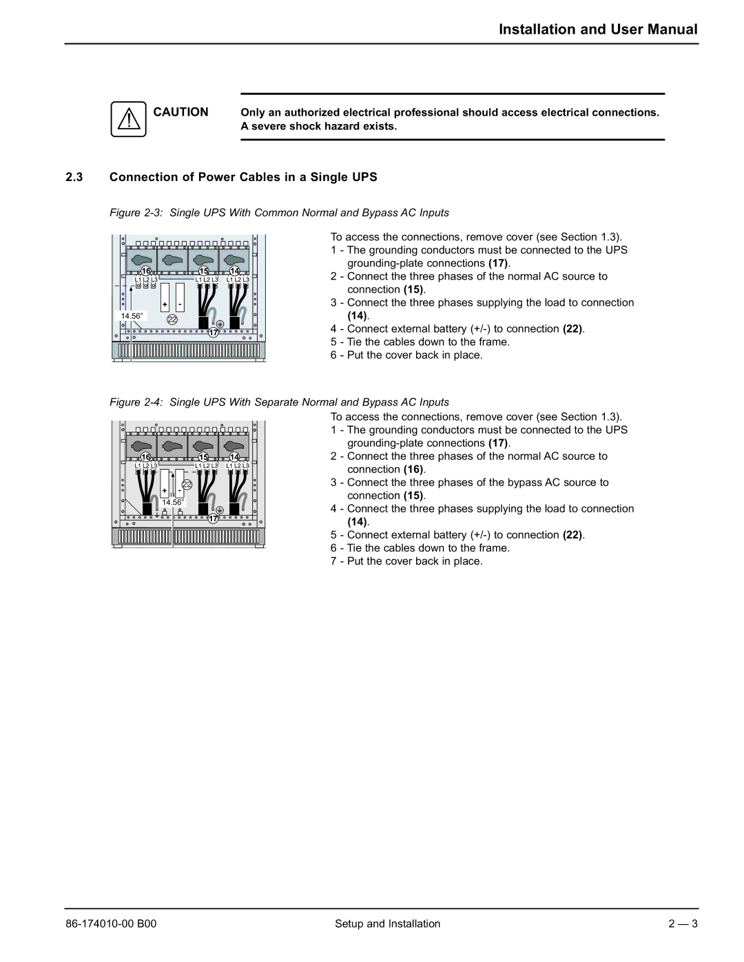
Figure 2-3: Single UPS With Common Normal and Bypass AC Inputs
14.56” | 22 |
|
To access the connections, remove cover (see Section 1.3).
1 - The grounding conductors must be connected to the UPS
2 - Connect the three phases of the normal AC source to connection (15).
3 - Connect the three phases supplying the load to connection (14).
4 - Connect external battery
5 - Tie the cables down to the frame.
6 - Put the cover back in place.
Figure 2-4: Single UPS With Separate Normal and Bypass AC Inputs
| To access the connections, remove cover (see Section 1.3). | ||
| 1 | - The grounding conductors must be connected to the UPS | |
|
| ||
| 2 | - Connect the three phases of the normal AC source to | |
|
| connection (16). | |
22 | 3 | - Connect the three phases of the bypass AC source to | |
14.56” |
| connection (15). | |
4 | - Connect the three phases supplying the load to connection | ||
| |||
|
| (14). | |
| 5 | - Connect external battery | |
| 6 | - Tie the cables down to the frame. | |
| 7 | - Put the cover back in place. | |
Setup and Installation | 2 — 3 |
