Installation and User Manual
2.9Routing the Control/Communications Cables
Single UPS
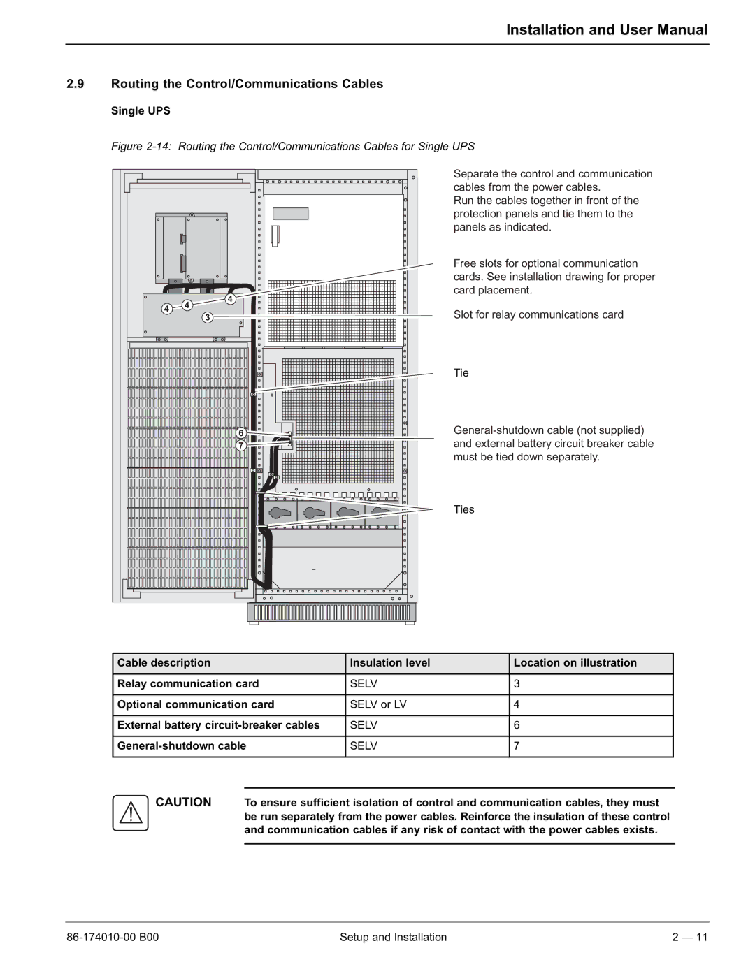
Figure 2-14: Routing the Control/Communications Cables for Single UPS
Separate the control and communication cables from the power cables.
Run the cables together in front of the protection panels and tie them to the panels as indicated.
Free slots for optional communication cards. See installation drawing for proper card placement.
Slot for relay communications card
Tie
Ties
Cable description | Insulation level | Location on illustration |
|
|
|
Relay communication card | SELV | 3 |
|
|
|
Optional communication card | SELV or LV | 4 |
|
|
|
External battery | SELV | 6 |
|
|
|
| SELV | 7 |
|
|
|
CAUTION To ensure sufficient isolation of control and communication cables, they must be run separately from the power cables. Reinforce the insulation of these control and communication cables if any risk of contact with the power cables exists.
Setup and Installation | 2 — 11 |