MGE Galaxy 5000
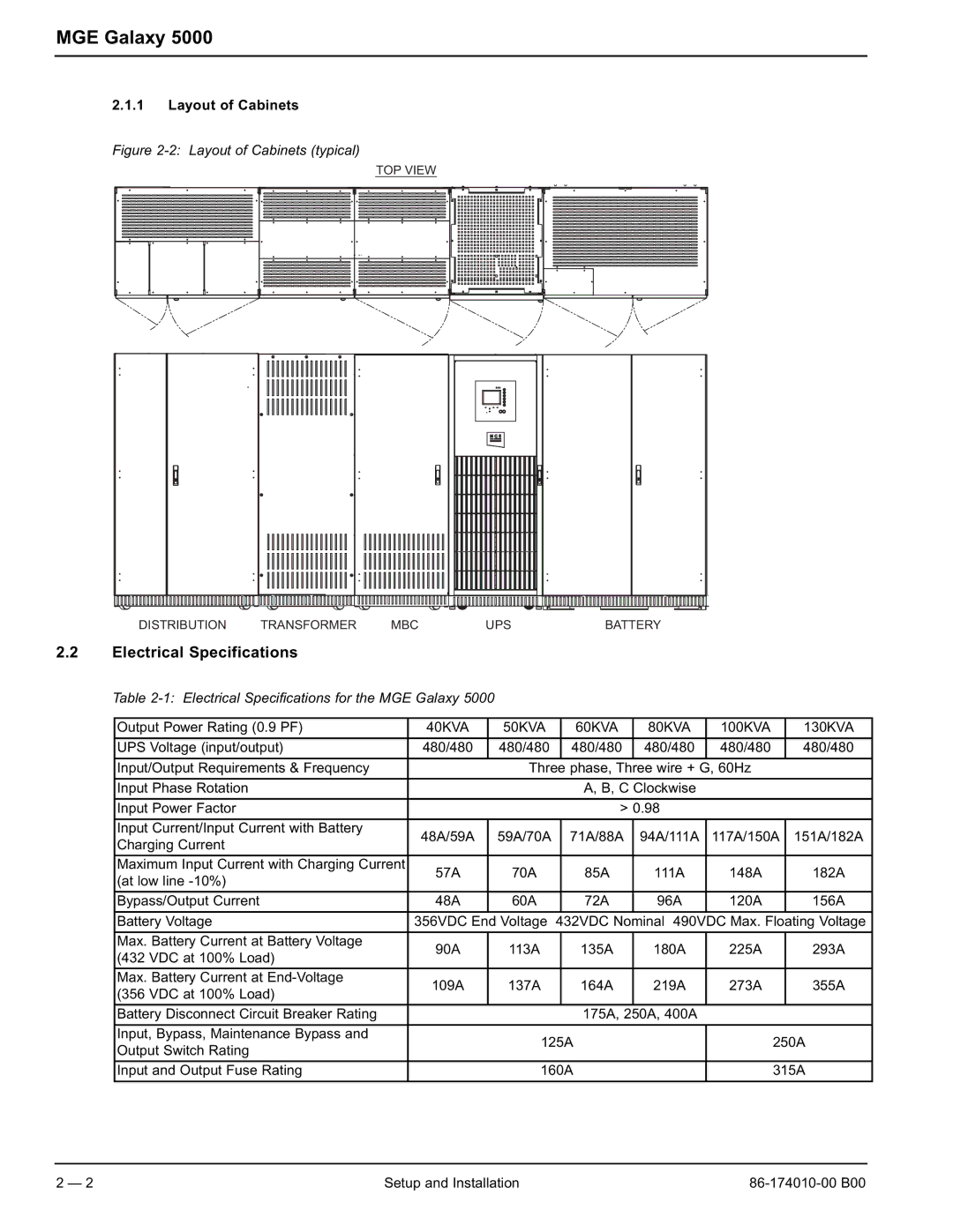
2.1.1Layout of Cabinets
Figure 2-2: Layout of Cabinets (typical)
TOP VIEW
DISTRIBUTION | TRANSFORMER | MBC | UPS | BATTERY |
2.2Electrical Specifications
Table 2-1: Electrical Specifications for the MGE Galaxy 5000
Output Power Rating (0.9 PF) | 40KVA | 50KVA |
| 60KVA | 80KVA | 100KVA | 130KVA |
|
|
|
|
|
|
|
|
UPS Voltage (input/output) | 480/480 | 480/480 |
| 480/480 | 480/480 | 480/480 | 480/480 |
|
|
|
|
|
|
| |
Input/Output Requirements & Frequency |
| Three phase, Three wire + G, 60Hz |
| ||||
|
|
|
|
|
|
| |
Input Phase Rotation |
|
|
| A, B, C Clockwise |
|
| |
|
|
|
|
|
| ||
Input Power Factor |
|
| > 0.98 |
|
| ||
|
|
|
|
|
|
|
|
Input Current/Input Current with Battery | 48A/59A | 59A/70A |
| 71A/88A | 94A/111A | 117A/150A | 151A/182A |
Charging Current |
| ||||||
|
|
|
|
|
|
| |
|
|
|
|
|
|
|
|
Maximum Input Current with Charging Current | 57A | 70A |
| 85A | 111A | 148A | 182A |
(at low line |
| ||||||
|
|
|
|
|
|
| |
|
|
|
|
|
|
|
|
Bypass/Output Current | 48A | 60A |
| 72A | 96A | 120A | 156A |
|
|
|
|
|
|
|
|
Battery Voltage | 356VDC End Voltage | 432VDC Nominal 490VDC Max. Floating Voltage | |||||
|
|
|
|
|
|
|
|
Max. Battery Current at Battery Voltage | 90A | 113A |
| 135A | 180A | 225A | 293A |
(432 VDC at 100% Load) |
| ||||||
|
|
|
|
|
|
| |
|
|
|
|
|
|
|
|
Max. Battery Current at | 109A | 137A |
| 164A | 219A | 273A | 355A |
(356 VDC at 100% Load) |
| ||||||
|
|
|
|
|
|
| |
|
|
|
|
|
|
|
|
Battery Disconnect Circuit Breaker Rating |
|
|
| 175A, 250A, 400A |
|
| |
|
|
|
|
|
|
|
|
Input, Bypass, Maintenance Bypass and |
| 125A |
| 250A | |||
Output Switch Rating |
|
| |||||
|
|
|
|
|
|
| |
|
|
|
|
| |||
Input and Output Fuse Rating |
| 160A |
| 315A | |||
|
|
|
|
|
|
|
|
2 — 2 | Setup and Installation |
