Installation and User Manual
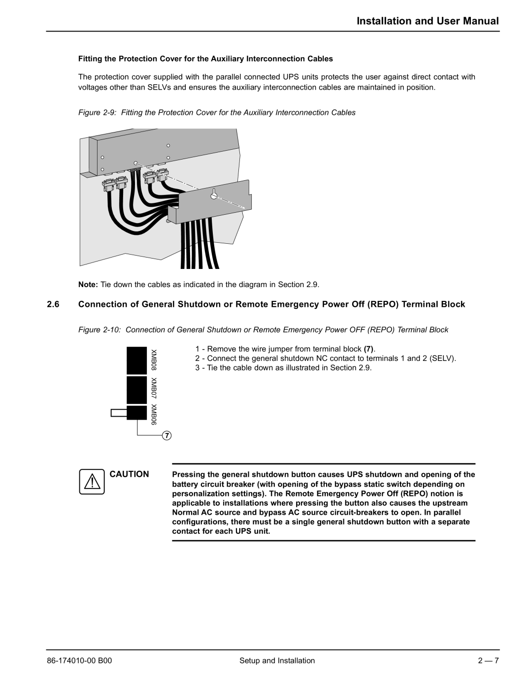
Fitting the Protection Cover for the Auxiliary Interconnection Cables
The protection cover supplied with the parallel connected UPS units protects the user against direct contact with voltages other than SELVs and ensures the auxiliary interconnection cables are maintained in position.
Figure 2-9: Fitting the Protection Cover for the Auxiliary Interconnection Cables
Note: Tie down the cables as indicated in the diagram in Section 2.9.
2.6Connection of General Shutdown or Remote Emergency Power Off (REPO) Terminal Block
Figure 2-10: Connection of General Shutdown or Remote Emergency Power OFF (REPO) Terminal Block
XMB08 XMB07 XMB06
1 - Remove the wire jumper from terminal block (7).
2 - Connect the general shutdown NC contact to terminals 1 and 2 (SELV). 3 - Tie the cable down as illustrated in Section 2.9.
CAUTION Pressing the general shutdown button causes UPS shutdown and opening of the battery circuit breaker (with opening of the bypass static switch depending on personalization settings). The Remote Emergency Power Off (REPO) notion is applicable to installations where pressing the button also causes the upstream Normal AC source and bypass AC source
Setup and Installation | 2 — 7 |