4-5. Connecting To Weld Output Terminals
4
1
| 2 |
Tools Needed: | 3 |
| |
3/4 in (19 mm) |
|
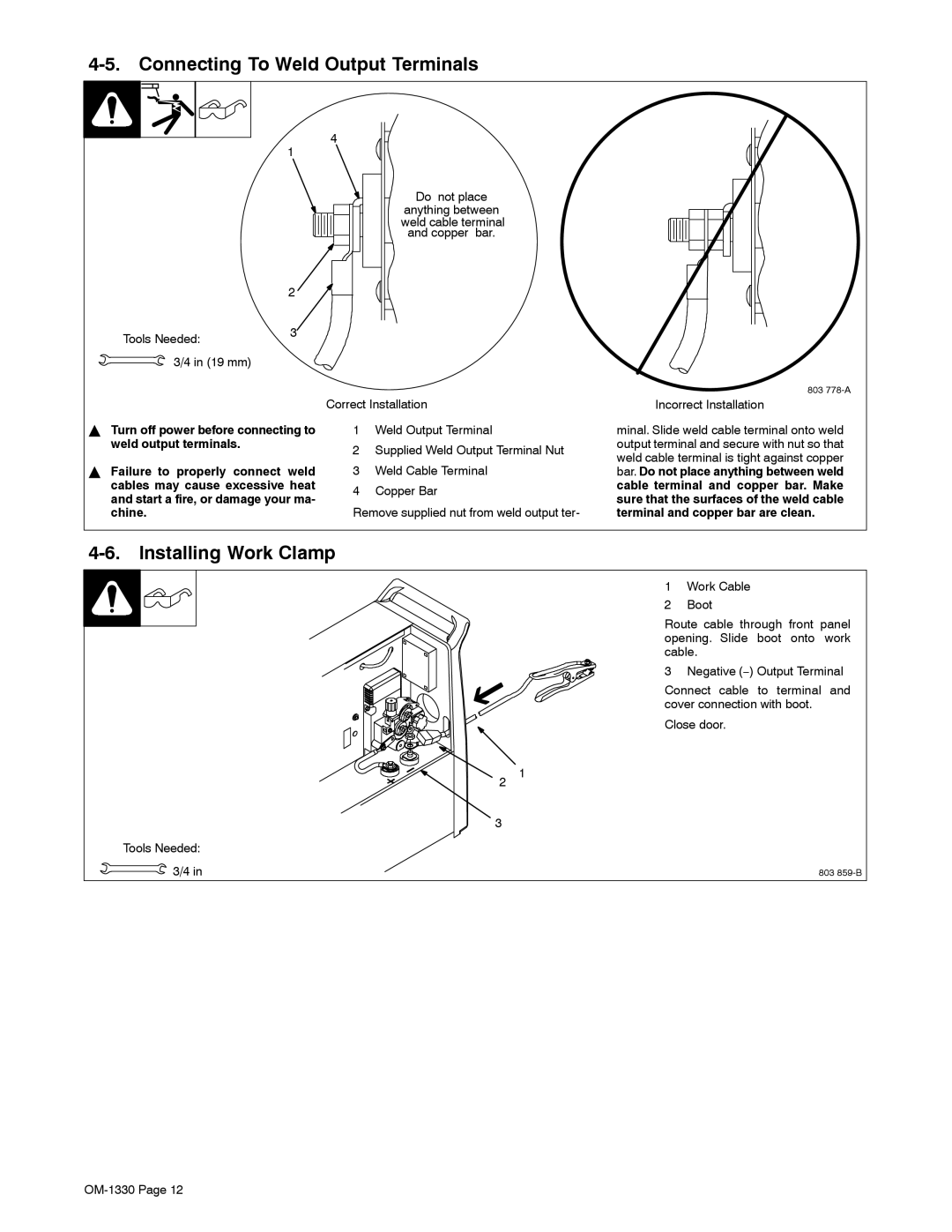
Do not place
anything between weld cable terminal and copper bar.
803
| Correct Installation | ||
Y Turn off power before connecting to | 1 | Weld Output Terminal | |
weld output terminals. | 2 | Supplied Weld Output Terminal Nut | |
| |||
Y Failure to properly connect weld | 3 | Weld Cable Terminal | |
cables may cause excessive heat | 4 | Copper Bar | |
and start a fire, or damage your ma- | |||
Remove supplied nut from weld output ter- | |||
chine. | |||
Incorrect Installation
minal. Slide weld cable terminal onto weld output terminal and secure with nut so that weld cable terminal is tight against copper bar. Do not place anything between weld
cable terminal and copper bar. Make sure that the surfaces of the weld cable terminal and copper bar are clean.
4-6. Installing Work Clamp
1 Work Cable
2 Boot
Route cable through front panel opening. Slide boot onto work cable.
3 Negative (−) Output Terminal
Connect cable to terminal and cover connection with boot.
Close door.
2 1
3
Tools Needed:
3/4 in | 803 |