Visit our website at
www.MillerWelds.com
| 2007−05 |
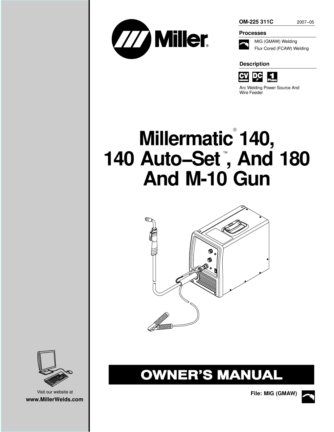
Processes
MIG (GMAW) Welding
Flux Cored (FCAW) Welding
Description
Arc Welding Power Source And
Wire Feeder
MillermaticR 140,
140 Auto−Set ™, And 180
And
Visit our website at
www.MillerWelds.com
| 2007−05 |
MIG (GMAW) Welding
Flux Cored (FCAW) Welding
Arc Welding Power Source And
Wire Feeder
MillermaticR 140,
140 Auto−Set ™, And 180
And