.A complete Parts List is available
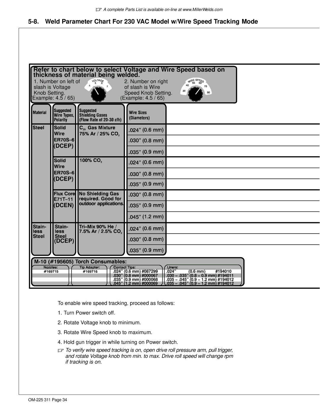
Refer to chart below to select Voltage and Wire Speed based on thickness of material being welded.
1. Number on left of | 2. Number on right |
slash is Voltage | of slash is Wire |
Knob Setting. | Speed Knob Setting. |
(Example: 4.5 / 65) | (Example: 4.5 / 65) |
(DCEP)
(DCEP)
(DCEN)
(DCEP)
|
|
|
|
|
|
|
|
|
|
|
|
|
| .024” (0.6 mm) #087299 .024” | (0.6 mm) | #194010 | |||
.030” (0.8 mm) #000067 .030 − .035” (0.8 − 0.9 mm) #194011
.035” (0.9 mm) #000068 .035 − .045” (0.9 − 1.2 mm) #194012
.045” (1.2 mm) #000069 .035 − .045” (0.9 − 1.2 mm) #194012
To enable wire speed tracking, proceed as follows:
1.Turn Power switch off.
2.Rotate Voltage knob to minimum.
3.Rotate Wire Speed knob to maximum.
4.Hold gun trigger in while turning on Power switch.
.To verify wire speed tracking is on, open drive roll pressure arm, pull trigger, and rotate Voltage knob from min. to max. Drive roll speed will change rpm if tracking is on.
