Description
OM-129 647W
Processes
From Miller to You
Table of Contents
Page
ARC Rays can burn eyes and skin
Symbol Usage
Arc Welding Hazards
Electric Shock can kill
Engine Hazards
Engine Heat can cause fire
Battery Explosion can Blind
Moving Parts can cause injury
Engine Exhaust Gases can kill
ARC Welding can cause interference
Principal Safety Standards
EMF Information
Radiation can cause interference
LES Fumées ET LES GAZ peuvent être dangereux
Signification des symboles
− Consignes DE Sécurité − Lire Avant Utilisation
UN Choc Électrique peut tuer
LE Bruit peut affecter l’ouïe
LE Soudage peut provoquer un in- cendie ou une explosion
DES Particules Volantes peuvent blesser les yeux
DES Pièces Chaudes peuvent provoquer des brûlures graves
LA Chute DE L’APPAREIL peut blesser
DES Organes Mobiles peuvent provoquer des blessures
’EXPLOSION DE LA Batterie peut
LA Chaleur DU Moteur peut pro- voquer un incendie
Consignes relatives aux stimulateurs cardiaques
Principales normes de sécurité
Information sur les champs électromagnétiques
LE Soudage À L’ARC risque de provoquer des interférences
− Definitions
− Specifications
Symbols And Definitions
Weld, Power, And Engine Specifications
1898 lb 861 kg Engine End
Dimensions, Weights, And Operating Angles
Curve shows typical fuel use under weld or power loads
Fuel Consumption
60% Duty Cycle At 500 Amperes Duty Cycle is Percentage
AC Auxiliary Power
Warranty Minutes Welding Minutes Resting
Duty Cycle And Overheating
CC/DC Standard CV/DC Models With CV Option
Volt-Ampere Curves
Optional AC Power Plant Curves
Location
− Installation
Installing Welding Generator
Do Not Lift Unit From End Airflow Clearance
Maintain proper level
Activating The Dry Charge Battery
When electrolyte is low, add
Charger
Tools Needed 1/2
Connecting The Battery
Engine Prestart Checks
Connect Negative − Cable Last
Selecting Weld Cable Sizes
Connecting To Weld Output Terminals
Remote A/V Control Receptacle RC3
Installing Ether Cylinder Optional Ether Starting Aid
After installing cylinder, wait at
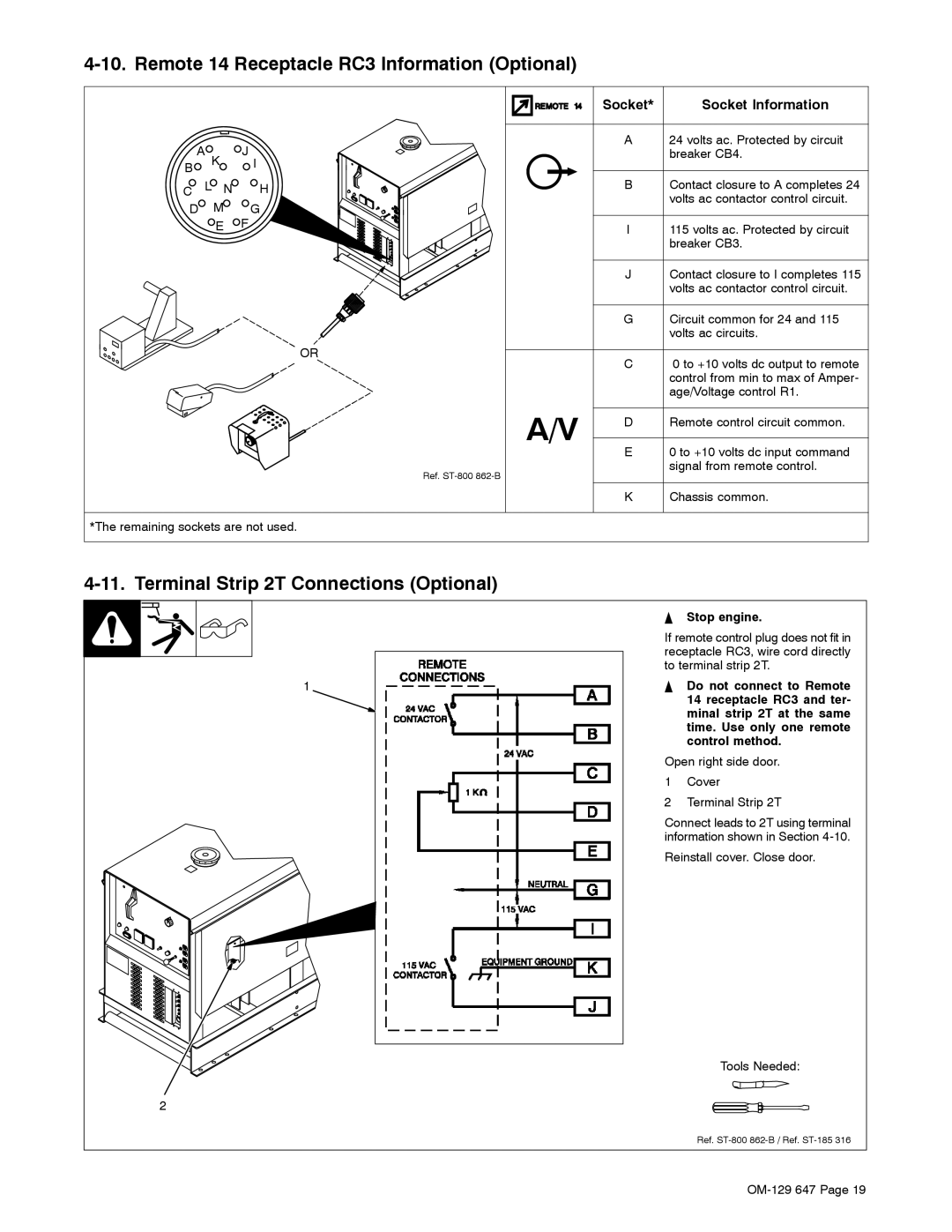
Stop engine
Remote 14 Receptacle RC3 Information Optional
Terminal Strip 2T Connections Optional
Socket
Standard Controls See Section
− Operating the Welding Generator
If light goes on, stop engine and check engine belt
Do not switch under load
Description Of Standard Controls See Section
If light goes off, stop engine and check oil level
Controls For Models With CV Option See Section
This unit has a max OCV control circuit
120 V 15 a AC Receptacle RC2 240 V 15 a AC Receptacle RC1
Auxiliary power is not affected by weld output
− Operating Auxiliary Equipment
Volt And 240 Volt Duplex Receptacles
British Receptacle Option
Optional Auxiliary Power Receptacles
Gfci Receptacle Option
Australian And South African Receptacle Options
Load Terminals
Connecting Optional Auxiliary Power Plant
Set Engine Control switch to Run when using auxiliary power
1011
− Maintenance & Troubleshooting
Deutz F3L912 Diesel Engine
Maintenance Label
Hose
Servicing Air Cleaner
To clean air filter
Servicing Fuel And Lubrication Systems
1850
Adjusting Engine Speed
Servicing Optional Ether Starting Aid
Stop engine To check belt tension
To adjust belt tension
Checking And Replacing Alternator Belt
13 mm Max Tools Needed 11/16
Resetting Fan Belt Safety Shutdown
Stop engine and let cool
Inspecting And Cleaning Optional Spark Arrestor Muffler
Stop engine and let cool. Reinstall cleanout plug
Overload Protection For Models With CV Option
Welding
Troubleshooting
Engine
Auxiliary Power
Trouble Remedy
OM-129 647
Circuit Diagram For Welding Generator Standard Models
− Electrical Diagrams
Circuit Diagram For Welding Generator Models With CV Option
184 954-C
Wetstacking
− RUN-IN Procedure
Load Bank
Run-In Procedure Using Load Bank
From flammables
Run-In Procedure Using Resistance Grid
Do not touch hot exhaust
Bank/grid
Grounding Generator To Truck Or Trailer Frame
− Auxiliary Power Guidelines
Selecting Equipment
Use ground device as stated in electrical codes
Grounding When Supplying Building Systems
How Much Power Does Equipment Require?
Earth ground if supplying
Farm/Home Equipment Rating Starting Watts Running Watts
Approximate Power Requirements For Industrial Motors
Approximate Power Requirements For Farm/Home Equipment
Industrial Motors Rating Starting Watts Running Watts
Contractor Rating Starting Watts Running Watts
Approximate Power Requirements For Contractor Equipment
KVA/HP x HP x 1000 = Starting Amperage Volts
Power Required To Start Motor
How Much Power Can Generator Supply?
Single-Phase Induction Motor Starting Requirements
Customer-supplied equipment is required if
Generator is to supply standby power during
Emergencies or power outages
Welding Generator Auxiliary Power output circuit
Selecting Extension Cord Use Shortest Cord Possible
101 100
− Parts List
66 65 102
Dia Part Description Quantity Mkgs
Optional
Panel, Front w/Components CC Model Illustrated
Panel, Front w/Components -1 Item
6 5
Generator
Generator -1 Item
Includes
171
Hardware is common Not available unless listed
Control Box CC/CV -1 Item 86 Optional
Panel, Mtg Components CC/CV Model
Panel, Mtg Components CC Model
Page
Support
Service
Your distributor also gives
For assistance in filing or settling claims
Miller Electric Mfg. Co
To locate distributor nearest you call 1-800-4-A-Miller