202. TV Connections
A/V Receiver
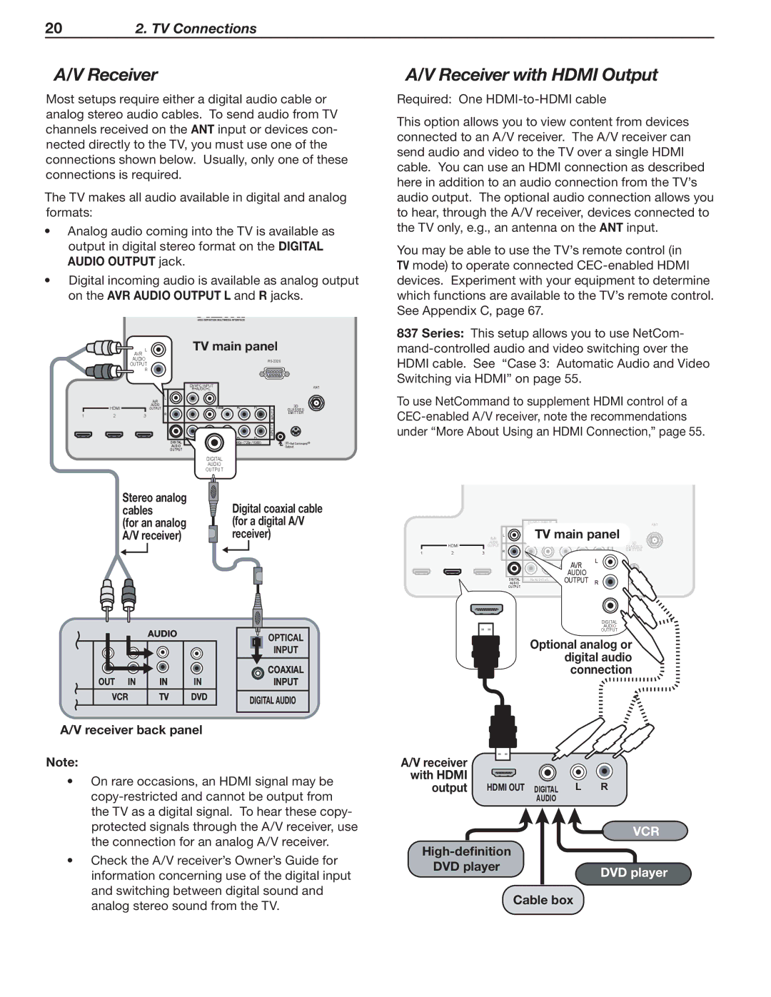
Most setups require either a digital audio cable or analog stereo audio cables. To send audio from TV channels received on the ANT input or devices con- nected directly to the TV, you must use one of the connections shown below. Usually, only one of these connections is required.
The TV makes all audio available in digital and analog formats:
•Analog audio coming into the TV is available as output in digital stereo format on the DIGITAL AUDIO OUTPUT jack.
•Digital incoming audio is available as analog output on the AVR AUDIO OUTPUT L and R jacks.
|
| AVR L |
|
| TV main panel |
| ||
|
| AUDIO |
|
|
|
|
| |
|
| OUTPUT |
|
|
|
|
|
|
|
| R |
|
|
|
|
|
|
|
|
|
|
| DVI/PC INPUT |
|
| ANT |
|
|
|
|
| R AUDIO L |
|
| |
|
|
|
|
|
|
|
| |
|
|
| AVR | L |
|
|
|
|
|
|
|
|
|
|
|
| |
| HDMI |
| AUDIO |
| Y/ VIDEO | Pb | Pr | 3D |
|
| OUTPUT |
| |||||
|
|
|
|
| 2 | GLASSES | ||
1 | 2 | 3 |
| R |
|
| INPUT | EMITTER |
|
|
|
| |||||
|
|
|
|
| Y/ VIDEO | Pb | INPUT 1 |
|
|
|
|
|
| Pr |
| ||
|
|
|
| DIGITAL | R AUDIO L | (480i / 480p / 720p / 1080i) | ||
|
|
|
| AUDIO |
|
|
| Output |
|
|
|
| OUTPUT |
|
|
|
|
|
|
|
|
| DIGITAL |
|
|
|
|
|
|
|
| AUDIO |
|
|
|
|
|
|
|
| OUTPUT |
|
|
|
Stereo analog | Digital coaxial cable |
cables | |
(for an analog | (for a digital A/V |
A/V receiver) | receiver) |
OPTICAL
INPUT
COAXIAL
INPUT
A/V receiver back panel
Note:
•On rare occasions, an HDMI signal may be
•Check the A/V receiver’s Owner’s Guide for information concerning use of the digital input and switching between digital sound and analog stereo sound from the TV.
A/V Receiver with HDMI Output
Required: One
This option allows you to view content from devices connected to an A/V receiver. The A/V receiver can send audio and video to the TV over a single HDMI cable. You can use an HDMI connection as described here in addition to an audio connection from the TV’s audio output. The optional audio connection allows you to hear, through the A/V receiver, devices connected to the TV only, e.g., an antenna on the ANT input.
You may be able to use the TV’s remote control (in TV mode) to operate connected
837 Series: This setup allows you to use NetCom-
To use NetCommand to supplement HDMI control of a
|
|
|
|
| DVI/PC INPUT |
|
|
| ANT |
|
|
|
|
| R AUDIO L |
|
|
| |
|
|
| AVR | L | TV main panel |
| |||
| HDMI |
| AUDIO |
| Y/ VIDEO | Pb | Pr |
| 3D |
|
| OUTPUT |
| 2 | |||||
|
|
|
|
|
| GLASSES | |||
1 | 2 | 3 |
| R |
|
| L | INPUT1 | EMITTER |
|
|
|
|
|
| ||||
|
|
|
|
|
| AVR |
| INPUT |
|
|
|
|
|
| Y/ VIDEO | AUDIO | Pr |
| |
|
|
|
|
|
|
| |||
|
|
|
| AUDIO | R AUDIO L | OUTPUT | R |
| Output |
|
|
|
| DIGITAL | (480i / 480p / 720p / 1080i) |
| |||
|
|
|
| OUTPUT |
|
|
|
|
|
DIGITAL
AUDIO
OUTPUT
Optional analog or digital audio connection
A/V receiver |
|
with HDMI |
|
output HDMI OUT DIGITAL L R | |
| AUDIO |
| VCR |
| |
DVD player | DVD player |
| |
| Cable box |