5. NetCommand IR Control | 51 |
IR Emitter Placement
The NetCommand system uses emitters connected to the
Replacement IR emitter cables are available for purchase from Mitsubishi. Request either part number 242D483020
1. Connect the plug end of the IR emitter cable to the |
| 1 |
|
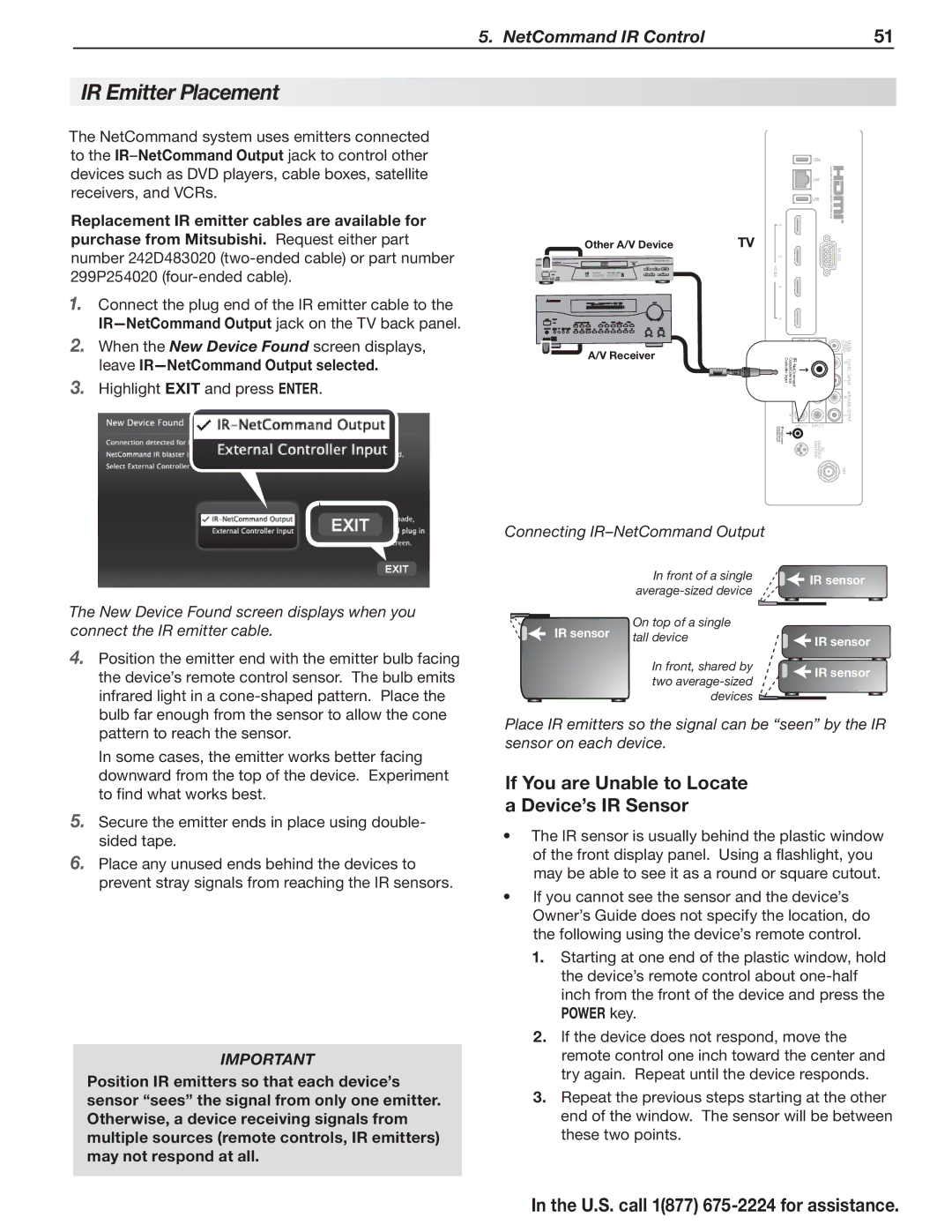
Other A/V Device | TV | |
| 2 | |
| HDMI |
|
| 3 |
|
| 4 |
|
2. | When the New Device Found screen displays, |
| leave |
3. | Highlight EXIT and press ENTER. |
A/V Receiver |
Controller | IR- |
Output/External Input | |
| NetCommand |
R |
| DIGITAL AUDIO OUTPUT |
L | IR- | R |
Controller | DVI/PC | |
Output/ExternalY/ Input | NetCommand | L |
VIDEO | INPUT | |
Pb |
| AVR R |
| AUDIO | |
|
| L |
Pr |
| OUTPUT |
INPUT 1 INPUT 2
EMITTERGLASSES3D
ANT
The New Device Found screen displays when you connect the IR emitter cable.
4.Position the emitter end with the emitter bulb facing the device’s remote control sensor. The bulb emits infrared light in a
In some cases, the emitter works better facing downward from the top of the device. Experiment to find what works best.
5.Secure the emitter ends in place using double- sided tape.
6.Place any unused ends behind the devices to prevent stray signals from reaching the IR sensors.
IMPORTANT
Position IR emitters so that each device’s sensor “sees” the signal from only one emitter. Otherwise, a device receiving signals from multiple sources (remote controls, IR emitters) may not respond at all.
Connecting IR–NetCommand Output
| In front of a single | IR sensor |
| ||
|
| |
IR sensor | On top of a single |
|
tall device |
| |
IR sensor | IR sensor | |
|
| |
| In front, shared by | IR sensor |
| two | |
|
| |
| devices |
|
Place IR emitters so the signal can be “seen” by the IR sensor on each device.
If You are Unable to Locate a Device’s IR Sensor
•The IR sensor is usually behind the plastic window of the front display panel. Using a flashlight, you may be able to see it as a round or square cutout.
•If you cannot see the sensor and the device’s Owner’s Guide does not specify the location, do the following using the device’s remote control.
1.Starting at one end of the plastic window, hold the device’s remote control about
2.If the device does not respond, move the remote control one inch toward the center and try again. Repeat until the device responds.
3.Repeat the previous steps starting at the other end of the window. The sensor will be between these two points.