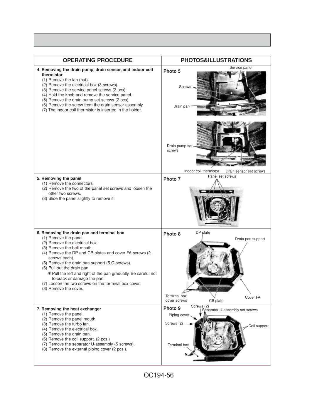
PL18FK21, PL30FK21, PL12FK1, PL36FK31, PL24FK21 specifications
Mitsubishi Electronics has long been recognized for its commitment to quality and innovation in the field of air conditioning systems. Among its impressive lineup, the models PL42FK21, PL24FK21, PL36FK31, PL12FK1, and PL30FK21 stand out for their advanced features, efficiency, and user-friendly designs.The PL42FK21 is designed to deliver superior cooling and heating performance, making it suitable for larger spaces. With its high energy efficiency rating, it minimizes energy consumption while providing optimal comfort. This model is equipped with advanced inverter technology that regulates the compressor speed, ensuring the desired temperature is maintained without unnecessary fluctuations in power usage.
Next, the PL24FK21 offers similar efficiencies while accommodating medium-sized spaces. This model incorporates a streamlined design that blends with any interior, while its quiet operation ensures that it does not disrupt daily activities. Moreover, the model features a programmable timer and remote control, enhancing user convenience and comfort.
The PL36FK31 is another model that brings forth powerful performance, ideal for commercial applications or larger residential installations. It boasts superior airflow distribution, ensuring even cooling or heating throughout the desired area. The addition of a high-performance filter system helps to purify the air, making it a healthy option for families and workplaces alike.
For those seeking a compact solution, the PL12FK1 is a standout choice. This model excels in efficiency while maintaining a small footprint, making it perfect for apartments or smaller rooms. With its energy-saving capabilities and modern design, this unit combines functionality and style seamlessly.
Finally, the PL30FK21 balances performance with affordability. This model comes with a host of features, including an eco-friendly refrigerant that minimizes environmental impact. It also incorporates smart controls that enable users to manage their settings via mobile apps, adding a level of modern convenience that many consumers desire.
Each of these Mitsubishi models is built with durability in mind, ensuring they can withstand the rigors of daily use. Additionally, Mitsubishi Electronics provides exceptional customer support and warranty options, reflecting their commitment to customer satisfaction.
In summary, the PL42FK21, PL24FK21, PL36FK31, PL12FK1, and PL30FK21 from Mitsubishi Electronics exemplify the brand's dedication to innovation, efficiency, and user-friendliness in air conditioning technology. These models cater to a variety of spaces and user needs, making them a reliable choice for both residential and commercial applications.

