An IR emitter cable is included with the TV.
The NetCommand system uses emitters connected to the IR—NetCommand Output jack to control other devices such as DVD players, cable boxes, satellite receivers, and VCRs.
1.Connect the plug end of the supplied IR emitter cable to the IR—NetCommand Output jack on the TV back panel.
2.Run the cable for each of the emitter ends under, alongside, or over each device to be controlled so that the emitter end is in front of the area where the remote control sensor is located.
3.Position the emitter end with the emitter bulb facing the remote control sensor. The bulb emits infrared light in a cone-shaped pattern. Place the bulb far enough from the sensor to allow the cone pattern to reach the sensor.
The IR sensor is usually behind the plastic window of the front display panel. It is sometimes visible with the aid of a flashlight and is normally a round or square cutout behind the plastic.
If you cannot see the sensor and the device’s Owner’s Guide does not specify the location, you can find it by following these steps using the device’s remote control:
a.Hold the device’s remote about one-half inch from the front of the device. Starting from one end of the display window plastic, press the POWER button.
b.If the device does not respond, move the remote control one inch toward the center and try again.
c.Repeat this until the device responds.
d.Note this location and then start over from the other end of the display window plastic, repeat- ing until the device responds again.
The remote control sensor is somewhere between these two positions. This is usually enough accuracy for placement of the IR emit- ters.
In some cases, the emitter works better facing downward from the top of the device. Experi- ment to find what works best.
5.Secure the emitter ends in place using double- sided tape.
6.Place any unused ends behind the devices to prevent stray signals from reaching the IR sensors.
| IR- | 3D | | | | | | | |
| | NetCommand R | | | | |
| Output / External | | | | | |
| GLASSES | | | | | | | |
| EMITTER | | | | | | | |
| Controller Input | | | | | |
| | AVR | | | | | | | |
| | AUDIO | | | | | | HDMI | |
| | OUTPUT | | | R AUDIO L | VIDEO | | VIDEO: 480i/480p/720p/1080i/1080p | �� |
| | DVI/PC INPUT | | AUDIO: PCM STEREO |
| | R | AUDIO | L | | 3 | IR-NetCommand | PC: VGA, W-VGA, SVGA, W-SVGA, |
| | L | | | | INPUT | XGA, W-ZGA, SXGA, 720p/ 1080p |
| | | | | | Output / External | HDMI | |
| ANT 2 / AUX | | | | Pb | Pr 2 | Controller Input | |
| R | | Y | 1 | 23 | |
| ANT 1 / MAIN | | | | INPUT | |
| | | | | | | | |
| | | | Y/VIDEO | Pb | Pr | | | |
| | | R AUDIO | L | (480i / 480p / 720p / 1080i) | S-VIDEO | | |
| | DIGITAL | INPUT 3 | | |
| | AUDIO | | | | | | | |
| | OUTPUT | | | | | | | |
| 57�#BDL�1BOFM | | | | | |
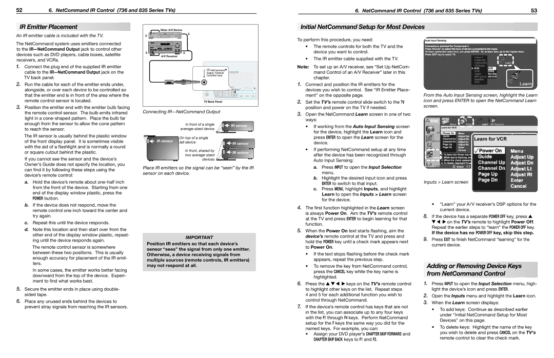
Connecting IR—NetCommand Output | | | | | | |
| *O�GSPOU�PG�B�TJOHMF� | | | | *3�TFOTPS� | |
| BWFSBHF�TJ[FE�EFWJDF | | | | |
| | | | | | | |
*3�TFOTPS� | 0O�UPQ�PG�B�TJOHMF� | | | | | | | | |
UBMM�EFWJDF | | | | | *3�TFOTPS� | |
| | | | | | |
| *O�GSPOU�TIBSFE�CZ� | | | | *3�TFOTPS� | |
| UXP�BWFSBHF�TJ[FE� | | | | |
| | | | | | | |
| EFWJDFT | | | | | | | |
Place IR emitters so the signal can be “seen” by the IR sensor on each device.
IMPORTANT
Position IR emitters so that each device’s sensor “sees” the signal from only one emitter. Otherwise, a device receiving signals from multiple sources (remote controls, IR emitters) may not respond at all.
To perform this procedure, you need:
•The remote controls for both the TV and the device you want to control.
•The IR emitter cable supplied with the TV.
Note: To set up an A/V receiver, see “Set Up NetCom- mand Control of an A/V Receiver” later in this chapter.
1.Connect and position the IR emitters for the devices you wish to control. See “IR Emitter Place- ment” on the opposite page.
2.Set the TV’s remote control slide switch to the TV position and power on the TV if needed.
3.Open the NetCommand Learn screen in one of two ways:
•If working from the Auto Input Sensing screen for the device, highlight the Learn icon and press ENTER to open the Learn screen for the device.
•If performing NetCommand setup at any time after the device has been recognized through Auto Input Sensing:
a.Press INPUT to open the Input Selection menu.
b.Highlight the desired input icon and press ENTER to switch to that input.
c.Press MENU, highlight Inputs, and highlight Learn to open the Inputs > Learn screen for the device.
4.The first function highlighted in the Learn screen is always Power On. Aim the TV’s remote control at the TV and press ENTER to begin learning for that function.
5.When the Power On text starts flashing, aim the device’s remote control at the TV and press and hold the POWER key until a check mark appears next to Power On.
•If the text stops flashing before the check mark appears, repeat the previous step.
•To remove the key from NetCommand control, press the CANCEL key while the key name is highlighted.
6.Press the 


 keys on the TV’s remote control to highlight other keys on the list. Repeat steps
4 and 5 for each additional function you wish to control through NetCommand.
7.If the device’s remote control has keys that are not in the list, you can associate up to any four keys with the F1 through F4 keys. Perform NetCommand setup for the F keys the same way you did for the named keys. For example, you can:
•Assign your DVD player’s CHAPTER SKIP FORWARD and CHAPTER SKIP BACK keys to F1 and F2.
From the Auto Input Sensing screen, highlight the Learn icon and press ENTER to open the NetCommand Learn screen.
Inputs > Learn screen
•“Learn” your A/V receiver’s DSP options for the current device.
8.If the device has a separate POWER OFF key, press 


 on the TV’s remote to highlight Power Off. Repeat the earlier steps to “learn” the POWER OFF key.
If the device has no POWER OFF key, skip this step.
9.Press EXIT to finish NetCommand “learning” for the current device.
Adding or Removing Device Keys from NetCommand Control
1.Press INPUT to open the Input Selection menu, high- light the device’s icon and press ENTER.
2.Open the Inputs menu and highlight the Learn icon.
3.When the Learn screen displays:
•To add keys: Continue as described earlier under “Initial NetCommand Setup for Most Devices” on this page.
•To delete keys: Highlight the name of the key you wish to delete and press CANCEL on the TV‘s remote control to clear the check mark.