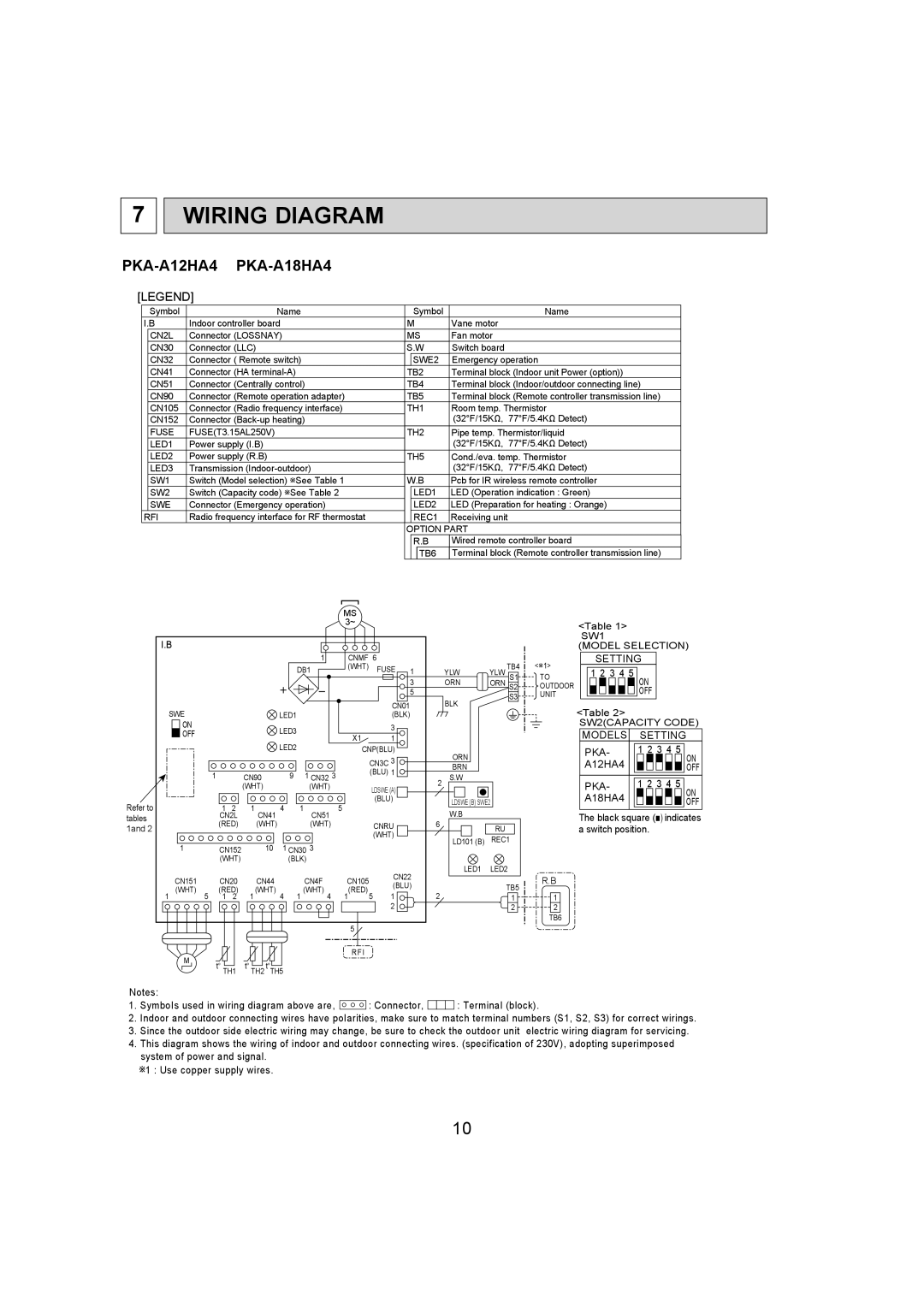
7 WIRING DIAGRAM

PKA-A12HA4

PKA-A18HA4


[LEGEND]


Symbol


Name


Symbol

Name


I.B

Indoor controller board

M

Vane motor


CN2L

Connector (LOSSNAY)

MS

Fan motor


CN30

Connector (LLC)

S.W

Switch board


CN32

Connector ( Remote switch)


SWE2

Emergency operation


CN41

Connector (HA terminal-A)

TB2

Terminal block (Indoor unit Power (option))


CN51

Connector (Centrally control)

TB4

Terminal block (Indoor/outdoor connecting line)


CN90

Connector (Remote operation adapter)

TB5

Terminal block (Remote controller transmission line)


CN105

Connector (Radio frequency interface)

TH1

Room temp. Thermistor


CN152

Connector (Back-up heating)


(32°F/15ΚΩ, 77°F/5.4ΚΩ Detect)


FUSE

FUSE(T3.15AL250V)

TH2

Pipe temp. Thermistor/liquid


LED1

Power supply (I.B)


(32°F/15ΚΩ, 77°F/5.4ΚΩ Detect)


LED2

Power supply (R.B)

TH5

Cond./eva. temp. Thermistor


LED3

Transmission (Indoor-outdoor)


(32°F/15ΚΩ, 77°F/5.4ΚΩ Detect)


SW1

Switch (Model selection) +See Table 1

W.B

Pcb for IR wireless remote controller


SW2

Switch (Capacity code) +See Table 2


LED1

LED (Operation indication : Green)


SWE

Connector (Emergency operation)


LED2

LED (Preparation for heating : Orange)


RFI

Radio frequency interface for RF thermostat


REC1

Receiving unit


OPTION PART


R.B

Wired remote controller board


TB6

Terminal block (Remote controller transmission line)


MS


3~


I.B


1

CNMF 6


<+1>


(WHT)

TB4

<Table 1> SW1

(MODEL SELECTION)

SETTING


DB1

FUSE

1

YLW

YLW

S1

TO


3

ORN

ORN

S2

OUTDOOR


CN01

5

BLK


S3

UNIT

SWE


LED1

(BLK)


1 2 3 4 5

<Table 2>

ON

OFF

ON


LED3


3


OFF


X1

1


LED2


CNP(BLU)


ORN


CN3C

3


BRN


1


9


1 CN32 3


(BLU)

1


CN90


S.W


2


(WHT)


(WHT)


LDSWE (A)


Refer to


1

2

1

4

1

5

(BLU)


LDSWE (B) SWE2


W.B


tables


CN2L

CN41


CN51


(RED)

(WHT)


(WHT)


CNRU

6


1and 2


RU


(WHT)


LD101 (B)

REC1


1


CN152

10

1 CN30 3


(WHT)


(BLK)


CN22


LED1

LED2


CN151


CN20

CN44


CN4F

CN105


R.B


(BLU)


TB5

(WHT)


(RED)

(WHT)


(WHT)


(RED)

2


1

5

1

2

1

4

1

4

1

5

1


1

1


2


2

2


TB6


5


M


RFI


TH1

TH2 TH5


SW2(CAPACITY CODE)

MODELS

SETTING

PKA-

1 2 3 4 5

A12HA4

ON

OFF

PKA-

1 2 3 4 5

A18HA4

ON

OFF

The black square () indicates a switch position.

Notes:

1.SymboIs used in wiring diagram above are, : Connector, : Terminal (block).

2.Indoor and outdoor connecting wires have poIarities, make sure to match terminal numbers (S1, S2, S3) for correct wirings.

3.Since the outdoor side electric wiring may change, be sure to check the outdoor unit electric wiring diagram for servicing.

4.This diagram shows the wiring of indoor and outdoor connecting wires. (specification of 230V), adopting superimposed system of power and signal.

+1 : Use copper supply wires.

10

Page 10
Image 10
Mitsumi electronic PKA-A12HA4, PKA-A18HA4 service manual Wiring Diagram, TB5

PKA-A18HA4, PKA-A12HA4 specifications

Mitsumi Electric Company is known for its innovations in the electronic components sector, and among its noteworthy products are the PKA-A18HA4 and PKA-A12HA4 components. Both models represent advancements in their respective categories, characterized by reliability, high performance, and cutting-edge technology.

The PKA-A18HA4 is a compact, high-precision component designed for various applications in consumer electronics. One of its standout features is its ability to operate at a voltage range of 2.7V to 5.5V, making it versatile for different devices. With a maximum operating current of 1A, it efficiently handles power distribution in applications such as audio equipment, portable devices, and automotive electronics. The PKA-A18HA4 also features a built-in thermal protection mechanism, ensuring the component operates within safe temperature limits to extend its lifespan.

Similarly, the PKA-A12HA4 is tailored for applications requiring low power consumption without compromising performance. It operates within a voltage range of 2.4V to 3.6V, making it ideal for battery-operated devices. This model not only offers an excellent balance between power efficiency and performance but also incorporates a range of built-in safety features, including over-voltage and short-circuit protection. These features enhance the reliability of devices utilizing the PKA-A12HA4 in environments where electrical fluctuations may occur.

Both models are also characterized by their compact footprint, allowing for easy integration into various electronic systems. Their designs prioritize minimal electromagnetic interference, which is crucial for maintaining signal integrity in sensitive applications. Additionally, they are manufactured using advanced semiconductor technologies that ensure high durability and robustness.

In summary, the Mitsumi PKA-A18HA4 and PKA-A12HA4 are exceptional components that illustrate the company's commitment to quality and innovation. Their unique features, including wide operating voltage ranges, safety mechanisms, and compact designs, make them suitable for a variety of applications across multiple industries. As technology continues to advance, these products embody the standards of performance and reliability that consumers expect from modern electronic components.