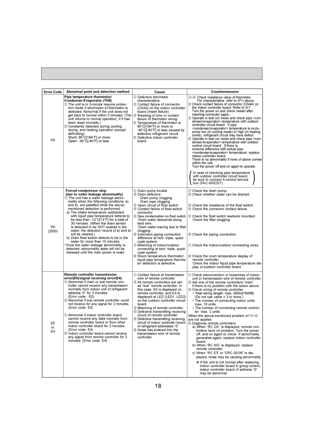
Error Code | Abnormal point and detection method | Cause | Countermeasure | |
| Pipe temperature thermistor/ | Defective thermistor | – Check resistance value of thermistor. | |
| Condenser-Evaporator (TH5) | characteristics | For characteristics, refer to (P1) above. |
| The unit is in 3-minute resume protec- | Contact failure of connector | Check contact failure of connector (CN44) on |
| tion mode if short/open of thermistor is | (CN44) on the indoor controller | the indoor controller board. Refer to 9-7. | |
| detected. Abnormal if the unit does not | board (Insert failure) | Turn the power on and check restart after |
| get back to normal within 3 minutes. (The | Breaking of wire or contact | inserting connector again. | |
| unit returns to normal operation, if it has | failure of thermistor wiring | Operate in test run mode and check pipe <con- |
| been reset normally.) | Temperature of thermistor is | denser/evaporator> temperature with outdoor |
| controller circuit board. If pipe | |
| Constantly detected during cooling, | | |
| | <condenser/evaporator> temperature is exclu- |
| drying, and heating operation (except | |
| | sively low (in cooling mode) or high (in heating |
| defrosting) | defective refrigerant circuit. |
| mode), refrigerant circuit may have defect. |
| | Defective indoor controller |
P9 | | Operate in test run mode and check pipe <con- |
| board |
| denser/evaporator> temperature with outdoor |
| | | control circuit board. If there is | |
| | | extreme difference with actual pipe | |
| | | <condenser/evaporator> temperature, replace |
| | | indoor controller board. | |
| | | There is no abnormality if none of above comes |
| | | within the unit. | |
| | | Turn the power off and on again to operate. |
| | | In case of checking pipe temperature | ) |
| | | with outdoor controller circuit board, |
| | | be sure to connect A-control service |
| | | (tool (PAC-SK52ST). |
| Forced compressor stop | Drain pump trouble | Check the drain pump. | |
| (due to water leakage abnormality) | Drain defective | Check whether water can be drained. | |
| The unit has a water leakage abnor- | · Drain pump clogging | | |
| mality when the following conditions, a) | · Drain pipe clogging | | |
| and b), are satisfied while the above- | Open circuit of float switch | Check the resistance of the float switch. |
| mentioned detection is performed. | Contact failure of float switch | Check the connector contact failure. | |
| a) The intake temperature subtracted | connector | | |
| with liquid pipe temperature detects to | Dew condensation on float switch | Check the float switch leadwire mounted. |
| be less than -10 [14 | ·Drain water descends along | Check the filter clogging. | |
| 30 minutes. (When the drain sensor | lead wire. | | |
PA | is detected to be NOT soaked in the | ·Drain water waving due to filter | | |
(2500) | water, the detection record of a) and b) | clogging. | Check the piping connection. | |
| will be cleared.) | Extension piping connection | |
| b) Drain float switch detects to be in the | difference at twin, triple, quad- | | |
| water for more than 15 minutes. | ruple system. | | |
| *Once the water leakage abnormality is | Miswiring of indoor/outdoor | Check the indoor/outdoor connecting wires. |
| detected, abnormality state will not be | connecting at twin, triple, quad- | | |
| released until the main power is reset. | ruple system. | Check the room temperature display of | |
| | Room temperature thermistor/ | |
| | liquid pipe temperature thermis- | remote controller. | |
| | tor detection is defective. | Check the indoor liquid pipe temperature dis- |
| | | play of outdoor controller board. | |
| | | |
| Remote controller transmission | Contact failure at transmission | Check disconnection or looseness of indoor |
| error(E0)/signal receiving error(E4) | wire of remote controller | unit or transmission wire of remote controller. |
| Abnormal if main or sub remote con- | All remote controllers are set | Set one of the remote controllers “main” |
| troller cannot receive any transmission | as “sub” remote controller. In | if there is no problem with the action above. |
| normally from indoor unit of refrigerant | this case, E0 is displayed on | Check wiring of remote controller. | |
| address “0” for 3 minutes. | remote controller, and E4 is | | |
| (Error code : E0) | displayed at LED (LED1, LED2) | (Do not use cable 3 or more.) | |
| Abnormal if sub remote controller could | on the outdoor controller circuit | • The number of connecting indoor units: |
| not receive for any signal for 2 minutes. | board. | max. 16 units | |
| (Error code: E0) | Miswiring of remote controller | • The number of connecting remote control- |
| Abnormal if indoor controller board | Defective transmitting receiving | ler: max. 2 units | |
| circuit of remote controller | When the above-mentioned problem of | ~ |
| cannot receive any data normally from | Defective transmitting receiving | are not applied, | |
E0 | remote controller board or from other | circuit of indoor controller board | Diagnose remote controllers. | |
or | indoor controller board for 3 minutes. | of refrigerant addresses “0”. | a) When “RC OK” is displayed, remote con- |
E4 | (Error code: E4) | Noise has entered into the | trollers have no problem. Turn the power |
| Indoor controller board cannot receive | transmission wire of remote | off, and on again to check. If abnormality |
| any signal from remote controller for 2 | controller. | generates again, replace indoor controller |
| minutes. (Error code: E4) | | board. | |
| | | b) When “RC NG” is displayed, replace |
| | | remote controller. | |
| | | c) When “RC E3” or “ERC 00-06” is dis- |
| | | played, noise may be causing abnormality. |
| | | If the unit is not normal after replacing |
| | | indoor controller board in group control, |
| | | indoor controller board of address “0” |
| | | may be abnormal. | |
| | | | |