Chapter 2 | Connection and Setup |
|
|
Network Configurations
The following are examples of network configurations. These samples show configurations using ana- log inputs and outputs. Momentum digital input and outputs or DSP devices use the same methods for network configuration.
Using the Momentum system, the network configuration possibilities are endless. For more information on advanced configurations and support, visit www.procomomentum.com. For further support, con- tact you local dealer or Pro Co technical support.
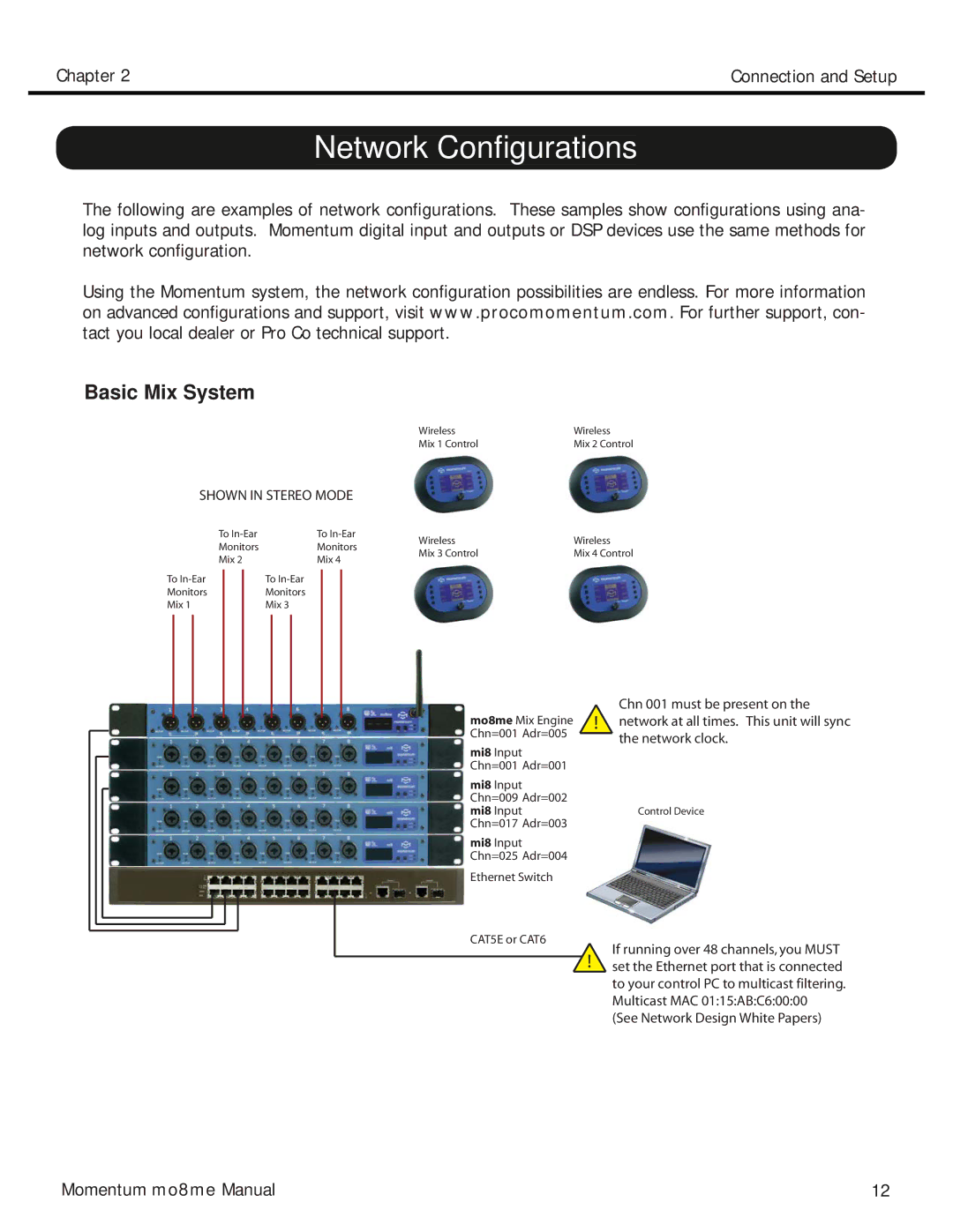
Basic Mix System
SHOWN IN STEREO MODE
To | To |
Monitors | Monitors |
Mix 2 | Mix 4 |
To | To |
Monitors | Monitors |
Mix 1 | Mix 3 |
Wireless | Wireless |
Mix 1 Control | Mix 2 Control |
Wireless | Wireless |
Mix 3 Control | Mix 4 Control |
mo8me Mix Engine Chn=001 Adr=005
mi8 Input Chn=001 Adr=001
mi8 Input Chn=009 Adr=002 mi8 Input Chn=017 Adr=003
mi8 Input Chn=025 Adr=004
Ethernet Switch
CAT5E or CAT6
Chn 001 must be present on the
!network at all times. This unit will sync the network clock.
Control Device
If running over 48 channels, you MUST
!set the Ethernet port that is connected to your control PC to multicast filtering. Multicast MAC 01:15:AB:C6:00:00 (See Network Design White Papers)
Momentum mo8me Manual | 12 |