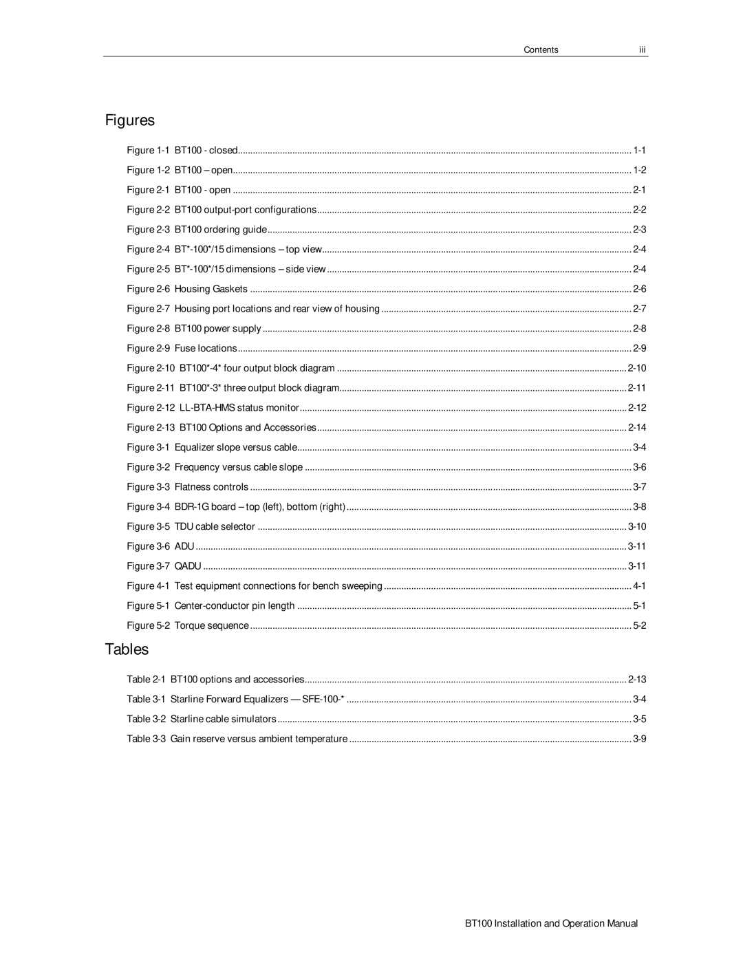
BT100 specifications
Motorola has long been a pioneer in telecommunications, and its BT100 model exemplifies the brand's commitment to innovation and reliability in the realm of Bluetooth technology. The Motorola BT100 is a Bluetooth headset that combines sleek design, advanced features, and robust performance, making it an ideal choice for users seeking hands-free convenience.One of the standout features of the BT100 is its impressive battery life. With a talk time of up to 10 hours, users can engage in long conversations without the constant need to recharge. Additionally, the standby time stretches up to 200 hours, meaning the headset can remain powered for extended periods when not in use. This makes it a great companion for those who are always on the go.
In terms of design, the Motorola BT100 boasts a lightweight and ergonomic structure that ensures comfort during prolonged use. Its adjustable and flexible ear hook allows for a secure fit, accommodating various ear shapes and sizes. The sleek profile of the headset also makes it visually appealing, allowing it to blend seamlessly with any outfit, whether professional or casual.
The sound quality of the Motorola BT100 is another significant aspect that deserves mention. The headset is equipped with noise-cancellation technology, which minimizes background noise and enhances the clarity of voice calls. This feature is particularly beneficial in busy environments or noisy settings, ensuring that users can communicate effectively without distractions.
Connectivity is seamless with the BT100, which utilizes Bluetooth 5.0 technology, providing a stable connection with a range of up to 33 feet. This allows users to move around freely without being tethered to their devices. The headset is compatible with a wide variety of smartphones, tablets, and laptops, making it a versatile accessory for any tech-savvy individual.
Moreover, the Motorola BT100 is user-friendly, featuring intuitive controls that enable easy management of calls and media playback. The headset supports voice commands, allowing users to keep their hands free while still accessing essential functions.
Overall, the Motorola BT100 combines functionality, style, and cutting-edge technology. Its impressive battery life, comfort-oriented design, exceptional sound quality, and seamless connectivity make it an ideal choice for anyone looking for a reliable Bluetooth headset. Whether for business, leisure, or everyday use, the BT100 stands as a testament to Motorola's expertise in crafting high-quality telecommunications devices.
