Section 2
Installation
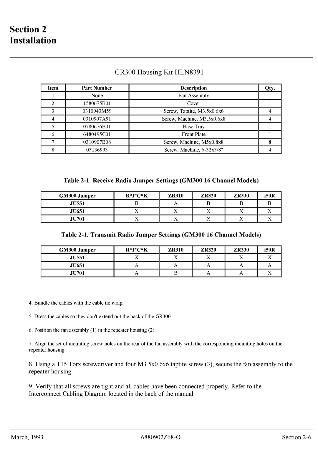
GR300 Housing Kit HLN8391_
Item | Part Number | Description | Qty. | |
1 | None | Fan Assembly | 1 | |
2 | 1580675B01 | Cover | 1 | |
3 | 0310943M59 | Screw, Taptite, M3.5x0.6x6 | 4 | |
4 | 0310907A91 | Screw, Machine, M3.5x0.6x8 | 4 | |
5 | 0780676B01 | Base Tray | 1 | |
6 | 6480495C01 | Front Plate | 1 | |
7 | 0310907B08 | Screw, Machine, M5x0.8x8 | 8 | |
8 | 03136993 | Screw, Machine, | 4 |
Table
GM300 Jumper
JU551
JU651
JU701
R*I*C*K
B
X
X
ZR310 | ZR320 | ZR330 |
A | B | B |
X | X | X |
X | X | X |
i50R
B
X
X
Table 2-1. Transmit Radio Jumper Settings (GM300 16 Channel Models)
GM300 Jumper | R*I*C*K | ZR310 | ZR320 | ZR330 | i50R | |
JU551 | X | X | X | X | X | |
JU651 | A | A | A | A | A | |
JU701 | A | B | A | A | X |
4.Bundle the cables with the cable tie wrap.
5.Dress the cables so they don't extend out the back of the GR300.
6.Position the fan assembly (1) in the repeater housing (2).
7.Align the set of mounting screw holes on the rear of the fan assembly with the corresponding mounting holes on the repeater housing.
8.Using a T15 Torx screwdriver and four M3.5x0.6x6 taptite screw (3), secure the fan assembly to the
repeater housing.
9.Verify that all screws are tight and all cables have been connected properly. Refer to the Interconnect Cabling Diagram located in the back of the manual.
March, 1993 | Section |