D |
|
|
|
|
|
|
|
|
|
13 | 14 | 15 16 | 17 | 18 | 19 |
| 22.Setting button | ||
|
|
|
|
|
|
| |||
12 |
|
|
|
|
|
|
|
| Used to confirm |
11 |
|
|
|
|
|
|
|
| the time of timer |
10 |
|
|
| MODE | FAN | SWING | 20 |
| and clock |
9 | AUTO |
|
| TEMP | HEALTH | 29 | 23.Sleep button | ||
8 |
|
|
|
|
|
| 21 |
| Used to set Sleep |
7 |
|
|
| CLOCK |
| SET |
| ||
6 |
|
|
|
|
|
| 22 |
| state |
SET |
|
| TIMER |
| SLEEP | 23 |
| ||
5 | SUR |
|
|
|
|
| 24.Time Adjusting | ||
|
|
|
|
| 24 | ||||
4 |
|
|
| FILTER RESETRESET |
| button | |||
|
|
|
|
|
| 25 |
| ||
3 |
|
|
|
|
|
| 26 |
| Used to adjust the |
|
|
| ON/OFF |
| 27 |
| time of timer and | ||
|
|
|
|
|
| ||||
|
|
|
|
|
|
|
| ||
2 |
|
|
|
|
|
| 28 |
| clock |
1 |
|
|
|
|
|
|
| ||
| 13.Sleep state display | 30 |
| 25.Reset button | |||||
1.ON/OFF button |
|
|
| ||||||
|
|
| When the wire | ||||||
Used to turn on/off unit |
| 14.Network control display |
| ||||||
2.Temperature display |
| 15.Working mode display |
|
| controller appears | ||||
3.Clock display |
| Working | Auto |
| Cooling Dehumidifying | Heating Fan |
| abnormal condition, | |
4.Timer ON/OFF display | mode | operation operation operation | operation operation | use a | |||||
Wire |
|
|
|
|
| article to press this | |||
5.Humidity display |
| controller |
|
|
|
|
| ||
|
|
|
|
|
|
|
| button to make the | |
6.Air filter cleaning display | 16.Electric heating display |
|
| ||||||
|
| wire controller | |||||||
When there is too much dust |
| 17.Operation mode button |
|
| resume normal | ||||
collected on the air inlet, the |
| Used to set working mode: |
| 26.Air Filter Reset | |||||
wire controller will show |
|
|
| ||||||
|
| Auto, Cooling, Dehumidifying, |
| button | |||||
this display to remind the |
|
|
| ||||||
user to clean the air inlet. |
|
| Heating, Fan |
|
| After cleaning the | |||
After cleaning and installation, |
| 18.Fan speed button |
|
| air inlet, press this | ||||
just press the air filter reset button. |
| Used to set fan speed: Low |
| button, the unit | |||||
7.Super/Soft operation display |
|
| |||||||
| Fan, Med Fan, High Fan, Auto |
| can start to operate | ||||||
8.Fan speed display |
|
| 19.Swing button |
| 27.Timer button | ||||
Auto |
| Used to set Auto Swing or | |||||||
|
|
|
| Used to set the | |||||
|
|
| Fixed air sending direction |
| |||||
Low Fan Med Fan High Fan Auto |
|
|
| mode of timer | |||||
| 20.Temperature Setting button |
| |||||||
9.Auto Swing display |
| 28.Lock state display | |||||||
|
| Used to set temperature, | |||||||
10.Health state display |
|
| 29.Health | ||||||
|
| temperature range: 16 C~30 C | |||||||
|
|
| Used to control the | ||||||
11.Fresh air state display |
| 21.Clock button |
|
| |||||
|
|
| generating oxygen | ||||||
12.Humidifying state display |
| Used to calibrate the time of |
| ||||||
|
| function and negative | |||||||
|
|
| timer and clock |
|
|
| |||
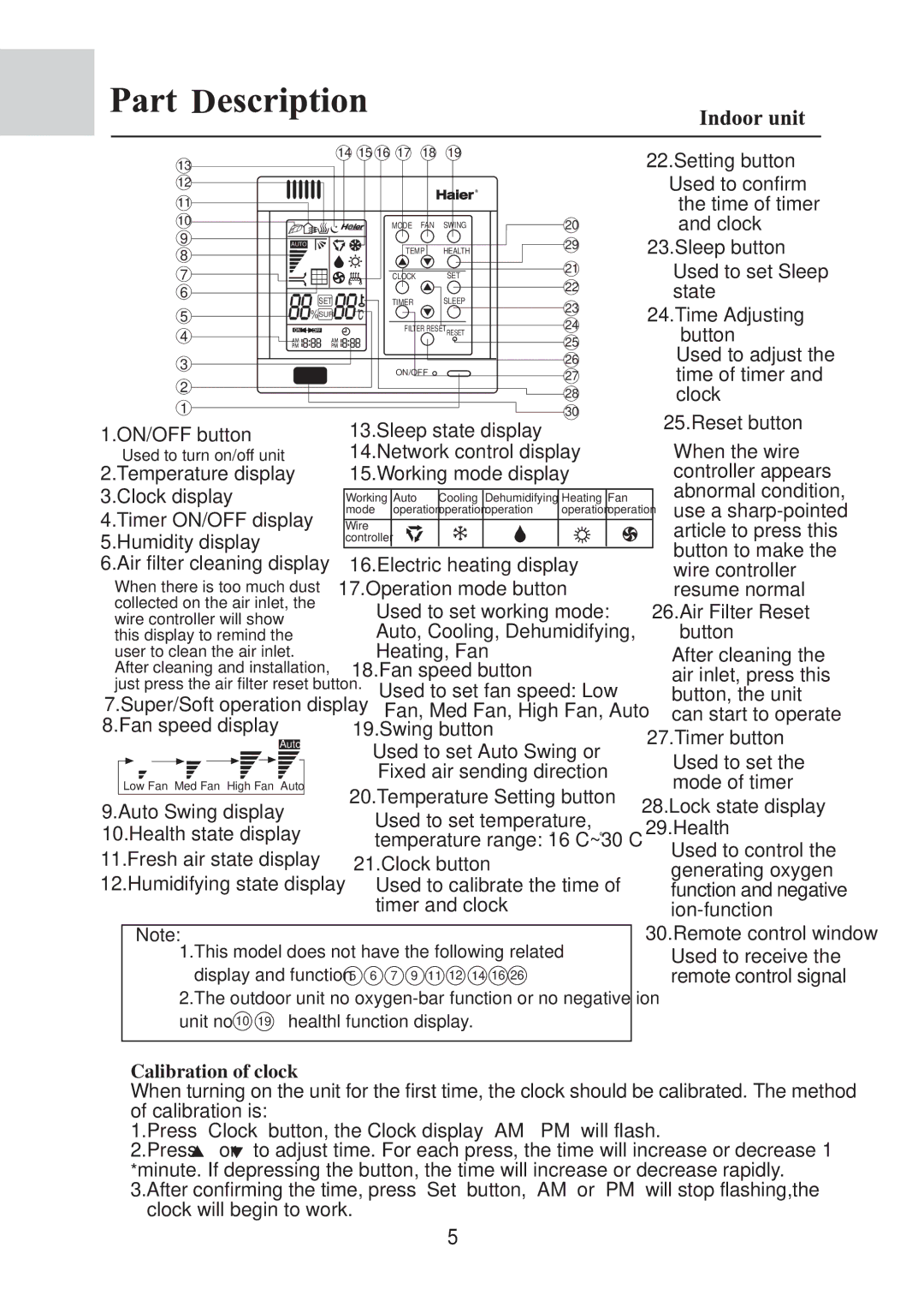
Note:
1.This model does not have the following related display and function 5 6 7 9 11 12 14 16 26
2.The outdoor unit no
unit no 10 19 healthl function display. |
30.Remote control window
Used to receive the remote control signal
Calibration of clock
When turning on the unit for the first time, the clock should be calibrated. The method of calibration is:
1.Press ìClockî button, the Clock display ìAMî ìPMî will flash.
2.Press ![]() or
or ![]() to adjust time. For each press, the time will increase or decrease 1 *minute. If depressing the button, the time will increase or decrease rapidly. 3.After confirming the time, press ìSetî button, ìAMî or ìPMî will stop flashing,the
to adjust time. For each press, the time will increase or decrease 1 *minute. If depressing the button, the time will increase or decrease rapidly. 3.After confirming the time, press ìSetî button, ìAMî or ìPMî will stop flashing,the
clock will begin to work.
5
