Installation Procedure
Electric wiring
Wire connection for built-in indoor unit
![]() Insert from outside the connection wire and signal transmission wire through the wall hole with pipeline already arranged.
Insert from outside the connection wire and signal transmission wire through the wall hole with pipeline already arranged.
![]() Pull out the front ends of connection wire and signal wire and make a circle on the signal wire.
Pull out the front ends of connection wire and signal wire and make a circle on the signal wire.
![]() Connect the connection wire according to the connection method and indoor and outdoor wiring diagram.
Connect the connection wire according to the connection method and indoor and outdoor wiring diagram.
![]() Pull the connecting conductor outwards slightly to confirm it is clamped tightly.
Pull the connecting conductor outwards slightly to confirm it is clamped tightly.
![]() Connect the plug for connecting the signal wire with the plug of the signal wire connected from the indoor unit.
Connect the plug for connecting the signal wire with the plug of the signal wire connected from the indoor unit.
![]() After wire connection is finished, install wire clips using the same method for connection wire clamping.
After wire connection is finished, install wire clips using the same method for connection wire clamping.
Note: When connecting the indoor unit and the outdoor unit, please do connect the wires with the same color terminals.
Notes:
![]() Before connecting the conductors between indoor unit and outdoor unit, check for the number on the indoor and outdoor units connecting terminals. Connect the terminals with the same color and number with a wire.
Before connecting the conductors between indoor unit and outdoor unit, check for the number on the indoor and outdoor units connecting terminals. Connect the terminals with the same color and number with a wire.
![]() Wrong connection would damage the controller of the air conditioner or the machine couldnt operate.
Wrong connection would damage the controller of the air conditioner or the machine couldnt operate.
![]() Do not connect the connection wire and signal wire with the same cable. They shall be connected respectively to ensure system normal operation.
Do not connect the connection wire and signal wire with the same cable. They shall be connected respectively to ensure system normal operation.
Field setting
Field setting the unit number
In order to realize central control of the MRV air conditioning system, its necessary to set the indoor unit number (control address).
Indoor unit number setting
Indoor unit number setting switch and confirmation of the settings.
There is a
Setting way is as follows:
Before connecting the power supply, please set the indoor unit number manually according to the following table
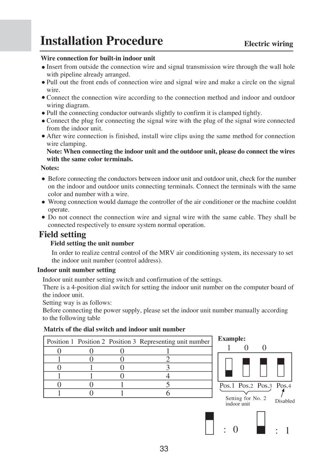
Matrix of the dial switch and indoor unit number
Position 1 Position 2 Position 3 Representing unit number
0 | 0 | 0 | 1 |
1 | 0 | 0 | 2 |
0 | 1 | 0 | 3 |
1 | 1 | 0 | 4 |
0 | 0 | 1 | 5 |
1 | 0 | 1 | 6 |
Example:
1 0 0
Pos.1 Pos.2 Pos.3 Pos.4
Setting for No. 2 | Disabled | |
indoor unit | ||
|
: 0
: 1
33