Installation Procedure
After selecting the unit installation location, proceed the following steps:
1.Drill a hole in the wall and insert the connecting pipe and wire through a PVC
2.Before drilling check that there is no pipe or reinforcing bar just behind the drilling position. Drilling shall avoid at positions with electric wire or pipe.
3.Mount the unit on a strong and horizontal building roof. If the base is not firm, it will cause noise, vibration or leakage (see Figure 6).
4.Support the unit firmly.
5.Change the form of the connection pipe, connection wire and drain pipe so that they can go through the wall hole easily.
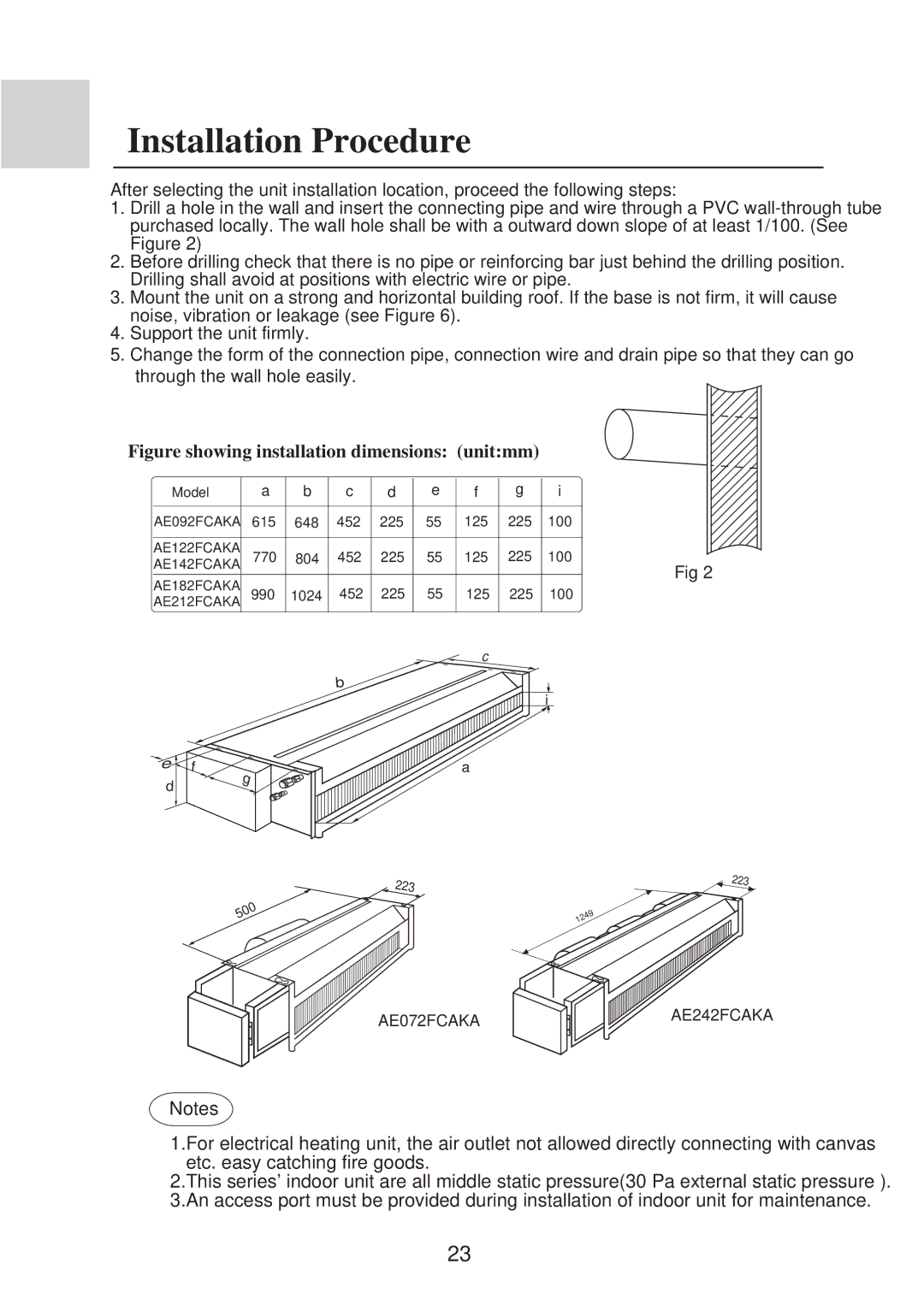
Figure showing installation dimensions: (unit:mm)
Model | a | b | c | d | e | f | g | i |
AE092FCAKA | 615 | 648 | 452 | 225 | 55 | 125 | 225 | 100 |
AE142FCAKAAE122FCAKA | 770 | 804 | 452 | 225 | 55 | 125 | 225 | 100 |
AE212FCAKAAE182FCAKA |
|
|
|
|
|
|
| Fig 2 |
990 | 1024 | 452 | 225 | 55 | 125 | 225 | 100 | |
|
|
|
|
|
| c |
|
|
|
|
| b |
|
|
|
| i |
|
|
|
|
|
|
|
|
e | f | g |
| ||
d |
| |
|
|
500
a
223
223
1249
AE072FCAKA
AE242FCAKA
Notes
1.For electrical heating unit, the air outlet not allowed directly connecting with canvas etc. easy catching fire goods.
2.This series' indoor unit are all middle static pressure(30 Pa external static pressure ). 3.An access port must be provided during installation of indoor unit for maintenance.
23