6

Maintaining

Your Snow

Thrower

WARNING

Before lubricating, repairing or inspecting, disengage all controls and stop engine. Wait until all moving parts have come to a complete stop. Remove the safety key to prevent unintended firing of the engine.

IMPORTANT

Refer to the Final Adjustment section of the Set-Up instructions after replacing drive and auger belts.

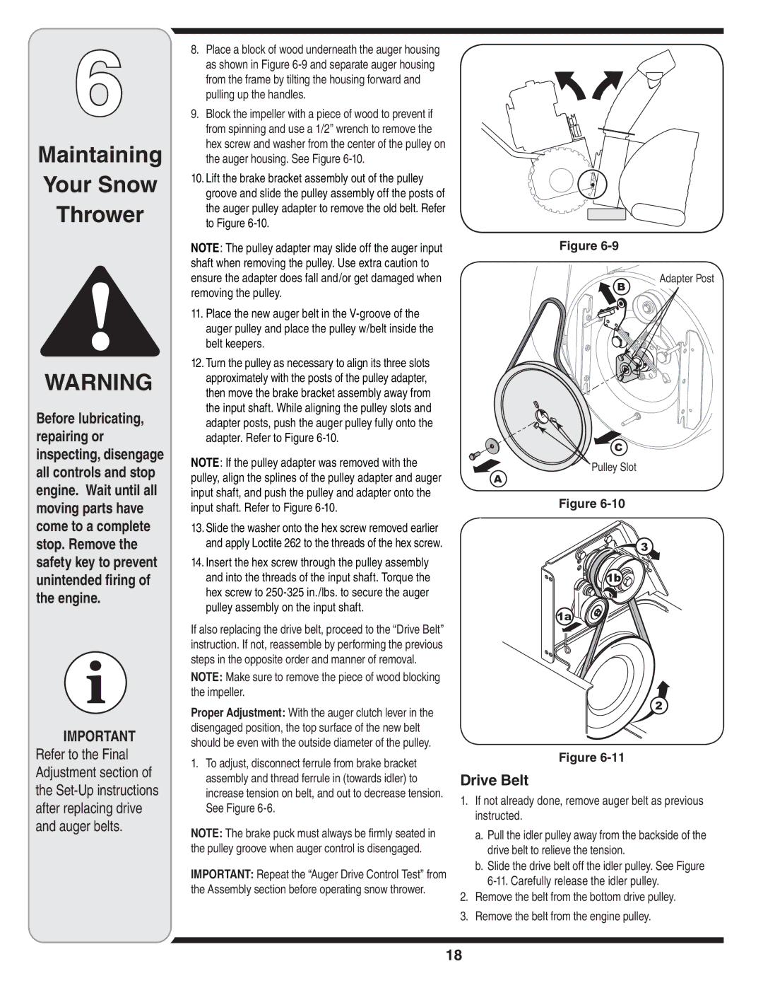
8.Place a block of wood underneath the auger housing as shown in Figure 6-9 and separate auger housing from the frame by tilting the housing forward and pulling up the handles.

9.Block the impeller with a piece of wood to prevent if from spinning and use a 1/2” wrench to remove the hex screw and washer from the center of the pulley on the auger housing. See Figure 6-10.

10.Lift the brake bracket assembly out of the pulley groove and slide the pulley assembly off the posts of the auger pulley adapter to remove the old belt. Refer to Figure 6-10.

NOTE: The pulley adapter may slide off the auger input shaft when removing the pulley. Use extra caution to ensure the adapter does fall and/or get damaged when removing the pulley.

11.Place the new auger belt in the V-groove of the auger pulley and place the pulley w/belt inside the belt keepers.

12.Turn the pulley as necessary to align its three slots approximately with the posts of the pulley adapter, then move the brake bracket assembly away from the input shaft. While aligning the pulley slots and adapter posts, push the auger pulley fully onto the adapter. Refer to Figure 6-10.

NOTE: If the pulley adapter was removed with the pulley, align the splines of the pulley adapter and auger input shaft, and push the pulley and adapter onto the input shaft. Refer to Figure 6-10.

13.Slide the washer onto the hex screw removed earlier and apply Loctite 262 to the threads of the hex screw.

14.Insert the hex screw through the pulley assembly and into the threads of the input shaft. Torque the hex screw to 250-325 in./lbs. to secure the auger pulley assembly on the input shaft.

If also replacing the drive belt, proceed to the “Drive Belt” instruction. If not, reassemble by performing the previous steps in the opposite order and manner of removal.

NOTE: Make sure to remove the piece of wood blocking the impeller.

Proper Adjustment: With the auger clutch lever in the disengaged position, the top surface of the new belt should be even with the outside diameter of the pulley.

1.To adjust, disconnect ferrule from brake bracket assembly and thread ferrule in (towards idler) to increase tension on belt, and out to decrease tension. See Figure 6-6.

NOTE: The brake puck must always be firmly seated in the pulley groove when auger control is disengaged.

IMPORTANT: Repeat the “Auger Drive Control Test” from the Assembly section before operating snow thrower.

Figure 6-9

B

Adapter Post


C

Pulley Slot

A

Figure 6-10

3

1b

1a

2

Figure 6-11

Drive Belt

1.If not already done, remove auger belt as previous instructed.

a.Pull the idler pulley away from the backside of the drive belt to relieve the tension.

b.Slide the drive belt off the idler pulley. See Figure 6-11. Carefully release the idler pulley.

2.Remove the belt from the bottom drive pulley.

3.Remove the belt from the engine pulley.

18

Page 18
Image 18
MTD 45, 33, 28 warranty Drive Belt, Pulley Slot

45, 33, 28 specifications

MTD (Machine Tool Division) has become synonymous with advanced machining solutions, particularly with its 28, 33, and 45 series, each designed for specific industrial applications yet sharing common core features that enhance performance and productivity.

The MTD 28 series is primarily focused on precision machining for small to medium components. One of its standout features is the high-speed spindle technology, which supports a range of drilling and milling operations with minimal downtime. The machine is equipped with a robust structure designed to absorb vibrations, ensuring high precision and surface finish quality. Additionally, the MTD 28 integrates an intuitive user interface, allowing operators to navigate complex machining processes with ease. The series supports multiple tool configurations, enabling rapid changeovers and versatility in production.

Moving to the MTD 33 series, this model is engineered for medium to large production runs. A key characteristic of the MTD 33 is its advanced automation capabilities, including automatic tool changers and integrated robotic systems. These technologies streamline operations, reducing cycle times significantly. The series also boasts enhanced thermal stability, which is crucial for maintaining accuracy in high-speed machining environments. Furthermore, the MTD 33 utilizes an adaptive control system that adjusts machine parameters in real-time, optimizing performance based on workload and material type.

The MTD 45 series is the flagship among them, designed for high-performance machining tasks in heavy industry. It features an expansive workspace and a powerful drive system that allows for the machining of large components with exceptional torque. This series utilizes advanced CNC controls, ensuring precision that meets industry standards. The MTD 45 is also equipped with advanced coolant and lubrication systems, enhancing tool life and ensuring optimal cutting conditions. Moreover, this model supports a variety of machining processes, including turning, milling, and grinding, further solidifying its versatility in diverse manufacturing settings.

In summary, the MTD 28, 33, and 45 series exemplify innovative engineering and user-centric design. With features like high-speed spindles, automation capabilities, and robust construction, these machines cater to varying production needs while ensuring precision and efficiency. Whether for small component fabrication or large scale industrial applications, MTD’s commitment to technological advancement enables businesses to achieve greater productivity and quality in their machining processes.