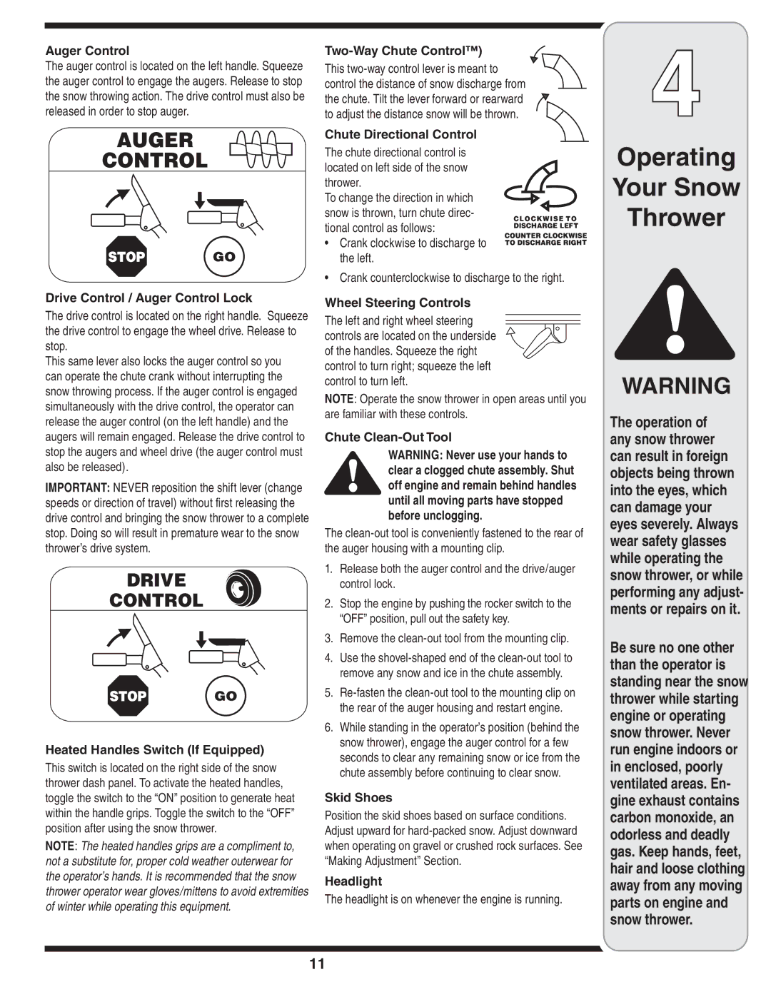
Auger Control

The auger control is located on the left handle. Squeeze the auger control to engage the augers. Release to stop the snow throwing action. The drive control must also be released in order to stop auger.

Two-Way Chute Control™)

This two-way control lever is meant to control the distance of snow discharge from the chute. Tilt the lever forward or rearward to adjust the distance snow will be thrown.

4

!5'%2

#/.42/,

'/

Chute Directional Control

The chute directional control is located on left side of the snow thrower.

To change the direction in which snow is thrown, turn chute direc- tional control as follows:

Crank clockwise to discharge to the left.

CLOCKWISE TO DISCHARGE LEFT

COUNTER CLOCKWISE TO DISCHARGE RIGHT

Operating

Your Snow

Thrower

Drive Control / Auger Control Lock

The drive control is located on the right handle. Squeeze the drive control to engage the wheel drive. Release to stop.

This same lever also locks the auger control so you can operate the chute crank without interrupting the snow throwing process. If the auger control is engaged simultaneously with the drive control, the operator can release the auger control (on the left handle) and the augers will remain engaged. Release the drive control to stop the augers and wheel drive (the auger control must also be released).

IMPORTANT: NEVER reposition the shift lever (change speeds or direction of travel) without first releasing the drive control and bringing the snow thrower to a complete stop. Doing so will result in premature wear to the snow thrower’s drive system.

$2)6%

#/.42/,

'/

Heated Handles Switch (If Equipped)

This switch is located on the right side of the snow thrower dash panel. To activate the heated handles, toggle the switch to the “ON” position to generate heat within the handle grips. Toggle the switch to the “OFF” position after using the snow thrower.

NOTE: The heated handles grips are a compliment to, not a substitute for, proper cold weather outerwear for the operator’s hands. It is recommended that the snow thrower operator wear gloves/mittens to avoid extremities of winter while operating this equipment.

• Crank counterclockwise to discharge to the right.

Wheel Steering Controls

The left and right wheel steering controls are located on the underside of the handles. Squeeze the right control to turn right; squeeze the left control to turn left.

NOTE: Operate the snow thrower in open areas until you are familiar with these controls.

Chute Clean-Out Tool

WARNING: Never use your hands to clear a clogged chute assembly. Shut off engine and remain behind handles until all moving parts have stopped before unclogging.

The clean-out tool is conveniently fastened to the rear of the auger housing with a mounting clip.

1.Release both the auger control and the drive/auger control lock.

2.Stop the engine by pushing the rocker switch to the “OFF” position, pull out the safety key.

3.Remove the clean-out tool from the mounting clip.

4.Use the shovel-shaped end of the clean-out tool to remove any snow and ice in the chute assembly.

5.Re-fasten the clean-out tool to the mounting clip on the rear of the auger housing and restart engine.

6.While standing in the operator’s position (behind the snow thrower), engage the auger control for a few seconds to clear any remaining snow or ice from the chute assembly before continuing to clear snow.

Skid Shoes

Position the skid shoes based on surface conditions. Adjust upward for hard-packed snow. Adjust downward when operating on gravel or crushed rock surfaces. See “Making Adjustment” Section.

Headlight

The headlight is on whenever the engine is running.

WARNING

The operation of any snow thrower can result in foreign objects being thrown into the eyes, which can damage your eyes severely. Always wear safety glasses while operating the snow thrower, or while performing any adjust- ments or repairs on it.

Be sure no one other than the operator is standing near the snow thrower while starting engine or operating snow thrower. Never run engine indoors or in enclosed, poorly ventilated areas. En- gine exhaust contains carbon monoxide, an odorless and deadly gas. Keep hands, feet, hair and loose clothing away from any moving parts on engine and snow thrower.

11

Page 11
Image 11
MTD 28, 45, 33 warranty $26% #/.42

45, 33, 28 specifications

MTD (Machine Tool Division) has become synonymous with advanced machining solutions, particularly with its 28, 33, and 45 series, each designed for specific industrial applications yet sharing common core features that enhance performance and productivity.

The MTD 28 series is primarily focused on precision machining for small to medium components. One of its standout features is the high-speed spindle technology, which supports a range of drilling and milling operations with minimal downtime. The machine is equipped with a robust structure designed to absorb vibrations, ensuring high precision and surface finish quality. Additionally, the MTD 28 integrates an intuitive user interface, allowing operators to navigate complex machining processes with ease. The series supports multiple tool configurations, enabling rapid changeovers and versatility in production.

Moving to the MTD 33 series, this model is engineered for medium to large production runs. A key characteristic of the MTD 33 is its advanced automation capabilities, including automatic tool changers and integrated robotic systems. These technologies streamline operations, reducing cycle times significantly. The series also boasts enhanced thermal stability, which is crucial for maintaining accuracy in high-speed machining environments. Furthermore, the MTD 33 utilizes an adaptive control system that adjusts machine parameters in real-time, optimizing performance based on workload and material type.

The MTD 45 series is the flagship among them, designed for high-performance machining tasks in heavy industry. It features an expansive workspace and a powerful drive system that allows for the machining of large components with exceptional torque. This series utilizes advanced CNC controls, ensuring precision that meets industry standards. The MTD 45 is also equipped with advanced coolant and lubrication systems, enhancing tool life and ensuring optimal cutting conditions. Moreover, this model supports a variety of machining processes, including turning, milling, and grinding, further solidifying its versatility in diverse manufacturing settings.

In summary, the MTD 28, 33, and 45 series exemplify innovative engineering and user-centric design. With features like high-speed spindles, automation capabilities, and robust construction, these machines cater to varying production needs while ensuring precision and efficiency. Whether for small component fabrication or large scale industrial applications, MTD’s commitment to technological advancement enables businesses to achieve greater productivity and quality in their machining processes.